This thread has been locked.

If you have a related question, please click the "Ask a related question" button in the top right corner. The newly created question will be automatically linked to this question.

RM46L852: Reconfigure SPI DMA on slave

Part Number: RM46L852

Hi

I made a test project whern I am using following code to receive data on RM44 where SPI is configured as slave with DMA enabled. Every thing is woirking perfectly fine, Everytime i send 32 bytes from master i get an interrupt at Slave.

/* USER CODE BEGIN (2) */
g_dmaCTRL g_dmaCTRLPKT_RX;
g_dmaCTRL g_dmaCTRLPKT_TX;
uint8_t TX_Data_Slave[32] = { 0x01, 0x02, 0x03, 0x04, 0x05, 0x06, 0x07, 0x08, 0x09, 0x0A, 0x0B, 0x0C, 0x0D, 0x0E, 0x0F, 0x10,
                             0x11, 0x12, 0x13, 0x14, 0x15, 0x16, 0x17, 0x18, 0x19, 0x1A, 0x1B, 0x1C, 0x1D, 0x1E, 0x1F, 0x20};

uint8_t RX_Data_Slave[32] = { 0 };

//uint16_t RX_Data_Slave[8]  = { 0 };
//void dmaConfigCtrlPacket(uint32 sadd,uint32 dadd,uint32 dsize);
void dmaConfigCtrlTxPacket (uint32 sadd, uint32 dadd, uint16 ElmntCnt, uint16 FrameCnt);
void dmaConfigCtrlRxPacket (uint32 sadd, uint32 dadd, uint16 ElmntCnt, uint16 FrameCnt);
/* USER CODE END */

int main(void)
{
/* USER CODE BEGIN (3) */

    /* Enable CPU Interrupt through CPSR */
    _enable_IRQ();

    spiInit();

//  enabling dma module : this brings DMA out of reset
    dmaEnable();

//  Enable Interrupt after reception of data
    dmaEnableInterrupt(DMA_CH0, BTC);     //Block transfer complete

//  assigning dma request: channel-0 with request line - 0 (SPI1 Receive DMA Request)
    dmaReqAssign(DMA_CH0,0);
    dmaReqAssign(DMA_CH1,1);

//  configuring DMA control packets
    dmaConfigCtrlTxPacket((uint32)TX_Data_Slave, (uint32)(&spiREG1->DAT1), 1, 32);
    dmaConfigCtrlRxPacket((uint32)(&spiREG1->BUF) ,(uint32)RX_Data_Slave,1, 32);

//  setting DMA control packets
    dmaSetCtrlPacket(DMA_CH0,g_dmaCTRLPKT_RX);
    dmaSetCtrlPacket(DMA_CH1,g_dmaCTRLPKT_TX);

//  setting the DMA channel to trigger on h/w request */
    dmaSetChEnable(DMA_CH0, DMA_HW);
    dmaSetChEnable(DMA_CH1, DMA_HW);

//  DMA_REQ_Enable On first received data, a DMA_Req will be send to DMA
    spiREG1->INT0 = 0x00010000;

    while(1)
    {


    }
/* USER CODE END */

    return 0;
}


/* USER CODE BEGIN (4) */

volatile uint8_t count = 0;

void dmaGroupANotification(dmaInterrupt_t inttype, uint32 channel)
{
    if (inttype == BTC)
    {
        count++;
     }

}

void dmaConfigCtrlRxPacket (uint32 sadd, uint32 dadd, uint16 ElmntCnt, uint16 FrameCnt)
{
    g_dmaCTRLPKT_RX.SADD = sadd;
    g_dmaCTRLPKT_RX.DADD = dadd;
    g_dmaCTRLPKT_RX.CHCTRL = 0;
    g_dmaCTRLPKT_RX.FRCNT = FrameCnt;
    g_dmaCTRLPKT_RX.ELCNT = ElmntCnt;
    g_dmaCTRLPKT_RX.ELDOFFSET = 0;
    g_dmaCTRLPKT_RX.ELSOFFSET = 0;
    g_dmaCTRLPKT_RX.FRDOFFSET = 0;
    g_dmaCTRLPKT_RX.FRSOFFSET = 0;
    g_dmaCTRLPKT_RX.PORTASGN = 4;
    g_dmaCTRLPKT_RX.RDSIZE = ACCESS_8_BIT;
    g_dmaCTRLPKT_RX.WRSIZE = ACCESS_8_BIT;
    g_dmaCTRLPKT_RX.TTYPE = FRAME_TRANSFER;
    g_dmaCTRLPKT_RX.ADDMODERD = ADDR_FIXED;
    g_dmaCTRLPKT_RX.ADDMODEWR = ADDR_INC1;
    g_dmaCTRLPKT_RX.AUTOINIT = AUTOINIT_ON;
}

void dmaConfigCtrlTxPacket (uint32 sadd, uint32 dadd, uint16 ElmntCnt, uint16 FrameCnt)
{
    g_dmaCTRLPKT_TX.SADD = sadd;
    g_dmaCTRLPKT_TX.DADD = dadd;
    g_dmaCTRLPKT_TX.CHCTRL = 0;
    g_dmaCTRLPKT_TX.FRCNT = FrameCnt;
    g_dmaCTRLPKT_TX.ELCNT = ElmntCnt;
    g_dmaCTRLPKT_TX.ELDOFFSET = 0;
    g_dmaCTRLPKT_TX.ELSOFFSET = 0;
    g_dmaCTRLPKT_TX.FRDOFFSET = 0;
    g_dmaCTRLPKT_TX.FRSOFFSET = 0;
    g_dmaCTRLPKT_TX.PORTASGN = 4;
    g_dmaCTRLPKT_TX.RDSIZE = ACCESS_8_BIT;
    g_dmaCTRLPKT_TX.WRSIZE = ACCESS_8_BIT;
    g_dmaCTRLPKT_TX.TTYPE = FRAME_TRANSFER;
    g_dmaCTRLPKT_TX.ADDMODERD = ADDR_INC1;
    g_dmaCTRLPKT_TX.ADDMODEWR = ADDR_FIXED;
    g_dmaCTRLPKT_TX.AUTOINIT = AUTOINIT_ON;
}
/* USER CODE END */

Now i want to reconfigure the DMA for different length (16 bytes), i tried to modify the DMA interrupt routine as shown below. Slave is receiving correct data but Master is receiving two extra bytes in the beginning of the buffer.

Slave sending -> { 0x01, 0x02, 0x03, 0x04, 0x05, 0x06, 0x07, 0x08, 0x09, 0x0A, 0x0B, 0x0C, 0x0D, 0x0E, 0x0F, 0x10, 0x11, 0x12, 0x13, 0x14, 0x15, 0x16}

Master receiving -> { 0x01, 0x02, 0x01, 0x02, 0x03, 0x04, 0x05, 0x06, 0x07, 0x08, 0x09, 0x0A, 0x0B, 0x0C, 0x0D, 0x0E, 0x0F, 0x10, 0x11, 0x12, 0x13, 0x14}

void dmaGroupANotification(dmaInterrupt_t inttype, uint32 channel)
{
    if (inttype == BTC)
    {
        count++;

        //  configuring DMA control packets
            dmaConfigCtrlTxPacket((uint32)TX_Data_Slave, (uint32)(&spiREG1->DAT1), 1, 16);
            dmaConfigCtrlRxPacket((uint32)(&spiREG1->BUF) ,(uint32)RX_Data_Slave,1, 16);

        //  setting DMA control packets
            dmaSetCtrlPacket(DMA_CH0,g_dmaCTRLPKT_RX);
            dmaSetCtrlPacket(DMA_CH1,g_dmaCTRLPKT_TX);

     }

}

Could you please let me know what am i missing, if possible could you please provide the code to reconfigure the DMA.

  • Hello,

    If the SPIENA signal is not used, the SPI master needs to wait for at least 6 VCLK cycles before sending  the clock to begin the transaction. 

  • Many Thanks for your quick reply, i m using following delay on master, which seems to be correct.

        /** - Delays */
        spiREG1->DELAY = (uint32)((uint32)250U << 24U)  /* C2TDELAY */
                       | (uint32)((uint32)0U << 16U)  /* T2CDELAY */
                       | (uint32)((uint32)0U << 8U)   /* T2EDELAY */
                       | (uint32)((uint32)0U << 0U);  /* C2EDELAY */

  • Does the SPI slave need such a big setup time (250 vclk cycles)? Does this delay help?

  • Hello Mr. Wang

    I kept it maximum possible, to give slave spi module enough time to be ready to receive data. But this is not working as well, 

    Could you please guide me what else should I do.

  • I'd like to double check that the delay is added in SPI master side rather than SPI slave side.

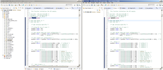
  • Good Point but the Delay is indeed on the Master side please have a look on the below image, left is Master (RM48) and right is slave (RM46)

  • It looks like that there SPI TXBUF is not empty when DMA is triggered.

  • The master is receiving two bytes which were sent in the starting position of previous communication, Once again notice the following pattern, 0x01 and 0x02 were at the start position, If you would have been right, the master would receive last two bytes of previous communication!!

    1) DMA configures for 32 bytes

    2) First iteration of communication (working correctly)

    Slave sending -> { 0x01, 0x02, 0x03, 0x04, 0x05, 0x06, 0x07, 0x08, 0x09, 0x0A, 0x0B, 0x0C, 0x0D, 0x0E, 0x0F, 0x10,
    0x11, 0x12, 0x13, 0x14, 0x15, 0x16, 0x17, 0x18, 0x19, 0x1A, 0x1B, 0x1C, 0x1D, 0x1E, 0x1F, 0x20}

    Master receiving ->{ 0x01, 0x02, 0x03, 0x04, 0x05, 0x06, 0x07, 0x08, 0x09, 0x0A, 0x0B, 0x0C, 0x0D, 0x0E, 0x0F, 0x10,
    0x11, 0x12, 0x13, 0x14, 0x15, 0x16, 0x17, 0x18, 0x19, 0x1A, 0x1B, 0x1C, 0x1D, 0x1E, 0x1F, 0x20}

    3) DMA reconfigured for 16 bytes.

    4) Second iteration of communication (not working properly)

    Slave sending -> { 0x01, 0x02, 0x03, 0x04, 0x05, 0x06, 0x07, 0x08, 0x09, 0x0A, 0x0B, 0x0C, 0x0D, 0x0E, 0x0F, 0x10};

    Master receiving -> 0x01, 0x02, 0x01, 0x02, 0x03, 0x04, 0x05, 0x06, 0x07, 0x08, 0x09, 0x0A, 0x0B, 0x0C, 0x0D, 0x0E}

    Can you try the same code at your end, This has become little urgent for me.

    Thankyou, 

  • Can you share your code?

  • Hello Devendra,

    Before the DMA is triggered, the RX/TX BUF and shift registers are not empty. When DMA is triggered, SPI master generates SPI clock, and data in shift register are moved out first. 

    You can disable SPI, then re-enable SPI before triggering DMA by setting bit 16 of INT0 register.

    spiREG1->GCR1 &= ~(0x1 << 24); //disable SPI
    spiREG1->GCR1 |= (0x1 << 24);    //enable SPI

    When the SPI is disabled (SPIEN bit is cleared) , the following SPI registers get forced to their default states:

    1. Both TX and RX shift registers
    2. The TXDATA fields of the SPI Transmit Data Register 0 (SPIDAT0) and the SPI Transmit Data Register 1 (SPIDAT1)
    3. All the fields of the SPI Flag Register (SPIFLG)
    4. Contents of SPIBUF and the internal RXBUF registers
  • Thanks for your insight,

    Sorry for my late reply, as there were Easter holidays, I would try this today and let you know the result,

    Have a nice day ahead.

  • Hello Mr Wang

    Disabling SPI before reconfiguring the DMA and enabling SPI after reconfiguring the DMA solved the issue, following is the code to be precise

    void dmaGroupANotification(dmaInterrupt_t inttype, uint32 channel)
    {
        if (inttype == BTC)
        {
            count++;
    
                spiREG1->GCR1 &= ~(0x1 << 24); //disable SPI
            //  configuring DMA control packets
                dmaConfigCtrlTxPacket((uint32)TX_Data_Slave, (uint32)(&spiREG1->DAT1), 1, 16);
                dmaConfigCtrlRxPacket((uint32)(&spiREG1->BUF) ,(uint32)RX_Data_Slave,1, 16);
    
            //  setting DMA control packets
                dmaSetCtrlPacket(DMA_CH0,g_dmaCTRLPKT_RX);
                dmaSetCtrlPacket(DMA_CH1,g_dmaCTRLPKT_TX);
                spiREG1->GCR1 |= (0x1 << 24);    //enable SPI
    
         }
    
    }
     

    Many Thanks for your support.

    Have a great day ahead.