This thread has been locked.

If you have a related question, please click the "Ask a related question" button in the top right corner. The newly created question will be automatically linked to this question.

EK-TM4C1294XL: External mode VREFP reference VREFA+ TP13 sources excessive current

Guru 54057 points
Part Number: EK-TM4C1294XL
Other Parts Discussed in Thread: TL431, TM4C1294NCPDT, , TLVH431

Internal reference VREFP = VDDA works as expected producing proper MCU temperature, dc current, dc voltage measurements ADC0/1.

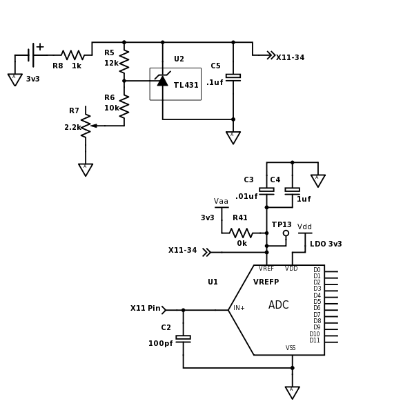
With R41 removed and 10Rk in series  X11 pin 34 for current limiting 3.3v reference @330ua the VREFA+ = 1vdc but sources 575ua with series 10R0 as VREFA+ tops out at 2.7vdc. Note worthy is the analog comparators ladder resistor chain also source VDDA and are configured in both internal reference and external reference modes.  

The external VREFA+ ADC0/1 reference at (TP13) drags down a TL431 precision voltage source limited to 3ma and powered via U5 +3v3 1 amp LDO regulator.

TM4C1294NCPDT data sheet table 27-45 list IVREF of 330.5ua MIN / 440ua MAX @3v3.

Why does EX-TM4C1294XL ADC0/1 VREFP require much more current externally versus internally configured? Is this normal for it to source so much current as it scares me to smoke MCU if hot wire X11 pin 34 without some value of series resistor to maintain current listed in table 27-45? 

  • Hi BP101,
    Just to make sure I understand your post, you sourced VREF+ from 3.3V with a 10K resistor and saw the voltage drop to 1.0V during a conversion. The 2.3V drop across 10K implies 230uA, which is within spec. Then you sourced it with 3.3V across the 1K (R8) shown in the schematic above. The TL431 is biased to trigger at around 5V, so it should not be conducting current. You saw 2.7V at X11-34. That implies VREF+ was consuming (3.3V-2.7)/1K = 600uA, well above the 440uA spec limit. If my understanding is correct, I will measure Ivrev+ with a current probe on the EK-TM4C1294XL I have here.
  • Hey Bob,

    Bob Crosby said:
    Just to make sure I understand your post, you sourced VREF+ from 3.3V with a 10K resistor and saw the voltage drop to 1.0V during a conversion.

    No I put a axial lead 10k in series with X11 REF Pin 34 with R41 removed then tested several series resistance at pin 43 down to 10 ohms, testing the VREFA+ load with DMM on micro amps. Afraid to go any lower as the TL431 R8 is set to limit current to 3ma MAX far above 440ua MAX. The TL431 formula for Vout = (1+R1/R2)*Vref roughly 1.4v-1.52v at scope lead. Shorted solder across 2.2k pot raised reference 2.8v loaded. 

    Just tested another EK has 3v3 precision voltage source input to REF pin 34 and voltage rises from 1v @197ua with 10k up to 2.8v with 10 ohms  @579ua measured in series with VREFA+ at pin 34. Strange thing is TP13 voltage jumps up to 3.2v during POR then falls back to 2.8v after the ADC reference is configured, something is not right it seems. Perhaps TL431L will reach 3.0v with no test series resistor at pin 34 but suspect current will peak 600ua or more or smoke the MCU at 3ma from R8. Even repowered the EK after changing test resistors but no difference other then TP13 jumps up to 3.2v then back down 2.8v. 

    Maybe external VREFA+ mode requires to also disable the internal ADC reference source in RCCG besides setting the VREFP to VREFA+ external?  

  • BP101 said:
    No I put a radial lead 10k in series with X11 REF Pin 43 with R41 removed

    X11-43 is pin PL-0, did you mean X11-34?

  • What is the voltage at the cathode of the TL431 when it is not connected to the Launchpad X11-34? Is it the expected 3.3V?
  • Hi Bob,

    I meant to say axial lead 10kR/10R  and will edit post but yes X11- pin 34. TP13 and TL431L output are one in the same when the MCU load is removed during POR?

    Only used TL431L being several on hand but like the LM4120-3v3 low drop out source over the TLVH431.

    To answer your question TL431L output also jumps up from 2.8v to 3.28v to 3.3v on POR depending on AC line power conditions. Await patiently to see what your current probe test results indicate but suspect the datasheet actually reflects internal sourced VREFP current consumption. The direction of current flow is hard for engineer to know being so little information of the VREFA+ input structure is disclosed, all we really know is VREFP can swing between VDDA or VREFA+.

  • Hi BP101,
    I got different results. Someone else had the current probe, so I removed R41 and soldered one end of a 13.3 Ohm 1% resistor to X11-34. I used a jumper wire to attach the other end of the resistor to the Launchpad 3.3V. (In effect, I have now connected VREF+ to 3.3V through a 13.3 Ohm resistor.) I measured the voltage drop across the resistor with a digital scope when doing an ADC conversion of channel 0 using the external reference. I measured a 5mV drop. The current I calculated was 5mV/13.3Ohms = 376uA. To verify that I was indeed using the external reference, I removed the jumper wire. My conversion value went from roughly 850 to 4095. When I changed to software to use the internal reference, the conversion result stayed the same (roughly 850) with or without the 3.3V on the resistor.
  • Hi Bob,

    Very interesting results but try putting a DMM in series with the 3v3 source as I was doing and current 10R was 570ua. Oddly the datasheet states we are both wrong for adding any resistor to limit VREFA+ current. Notes are not shown in the ADC electrical section rather in table 27-34 note (c) and 27-37 note (b).

    That seems to infer R41 (0R) would allow full supply current if we switch VREFP to VREFA+ @3v3 source?

    27.14 Input/Output Pin Characteristics
    Under Table 27-34 and 27-37
    b/c. Note that for the ADC's external reference inputs, care must be taken to avoid a current limiting resistor (refer to IVREF
    spec in Table 27-44 on page 1861)
  • I absolutely agree that adding a resistance to the VREFA+ source is the wrong thing to do. Since the current Irefa+ will vary with process, even a precision resistor would affect the conversion results. I assumed (and yes, as my horse owning wife points out, that makes me a less noble beast of burden) that the purpose of this experiment was to verify the current.

    Forgive me for asking this so late in the thread, but what is your purpose in the circuit above? If it is for ESD protection, would not a device like TPD1E05U06-Q1 be simpler?

  • I used a DMM (Fluke 8845A 6-1/2 digit multimeter) to measure the current. On my board it measured 352.963uA. Asserting reset, the current dropped to 0.0227uA. When I looked at it with the scope, it was a DC voltage across the 13.3 Ohm resistor, which makes sense since VREFA+ is simply biasing an internal resistor ladder used as the reference during the conversion.
  • Bob Crosby said:
    I absolutely agree that adding a resistance to the VREFA+ source is the wrong thing to do

    To me the 440ua MAX means if the VREFA+ input was allowed to source/sink more current it will destroy the ADC. The purpose for TL431 was to regulate voltage level and R3 limit current Cathode (Ika) to 3ma. If the intent of the datasheet table 27-44 is to inform us of current consumption perhaps it should state the ADC will not consume more than 440ua MAX in conversions, not that IVREF should be restricted to 440ua MAX. How would we know what VREFA+ does inside the ADC and if any current over 440ua might harm the ADC, being the ladder you mention is not illustrated in Figure 15-7 nor even elaborated in text.

    BTW: When I past switched VREFP to source VREFA+ with R41=0R the conversion values varied significantly. That was why I changed R41 to 10k added Cref caps but never used VREFA+ other than to filter out PWM in the low pass filter. Feel silly after finding note (b/c) not to add VREFA+ series resistance but obviously located in a table that has noting to do with the ADC electrical specifications.

    The DMM micro amps auto scale was reading 0.190ua - 0.570ua and now think that actually was 190na - 570na?  

  • Checked VREFA+ current again X11-pin 34 with 10R direct to +3v28 LDO and current is 700ua also has 7ma drop across 10R. Must be imagining DMM decimal point was there yesterday, Tenma DMM only scales down to micro amps.

    Good thing is the EK-TM4C1294XL LDO voltage stays at 3.28v when loaded VREFA+ but 440ua MAX does not exist on 4 different launch pads.

    Have to wonder if the Analog comparator +Vref rail sourcing VDDA has something to do with higher current readings?
  • The Cref parallel decoupling caps (1uf, 0.01uf) are not include on the EK-TM4C1294XL near TP13, perhaps why the ADC conversion was so off in the past testing of VREFA+.

    Even VREFA+ measuring 700ua and guessing even higher without any external series resistor, the external reference is not to far off from the internal reference conversion results. That better result only after Cref decoupling caps are added.

    Sure would like to know why the datasheet lists IVREF should not exceed 400ua when I have brand new launch pads that sink well over 550ua.  

  • BTW:

    Perhaps is a bad idea (TL431) precision reference to provided VREFA+ voltage source, R41 removed. Notes (B/C) missing under ADC electrical specifications states NOT to add VREFA+ series resistance. That idea seems obscure given the context of the datasheet IVREF MIN/MAX specification.