Tool/software: TI C/C++ Compiler
Hi Charles
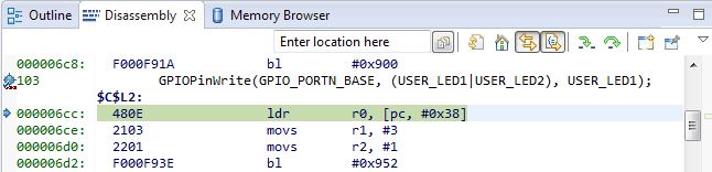
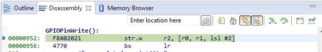
Why is there a delay of 800ns when entering an ISR? ?
Attach source code and measurement waveform
//includes
#include <stdint.h> // Variable definitions for the C99 standard.
#include <stdio.h> // Input and output facilities for the C99 standard.
#include <stdbool.h> // Boolean definitions for the C99 standard.
#include "inc/tm4c123gh6pge.h" // Definitions for the interrupt and register assignments.
#include "inc/hw_memmap.h" // Memory map definitions of the Tiva C Series device.
#include "inc/hw_types.h" // Definitions of common types and macros.
#include "inc/hw_gpio.h"
#include "driverlib/sysctl.h" // Definitions and macros for System Control API of DriverLib.
#include "driverlib/interrupt.h" // Defines and macros for NVIC Controller API of DriverLib.
#include "driverlib/gpio.h" // Definitions and macros for GPIO API of DriverLib.
#include "driverlib/timer.h" // Defines and macros for Timer API of DriverLib.
#include "driverlib/pin_map.h" //Mapping of peripherals to pins for all parts.
#include "driverlib/uart.h" // Definitions and macros for UART API of DriverLib.
#include "driverlib/adc.h" // Definitions for ADC API of DriverLib.
#include "driverlib/fpu.h" // Prototypes for the FPU manipulation routines.
#include "utils/uartstdio.h" // Prototypes for the UART console functions.
                             // Needs to add "utils/uartstdio.c" through a relative link.
//definitions
#define UART1_BAUDRATE      115200  // UART baudrate in bps

// function prototypes
void init_timer(void);
void duty_cycle(void);
void init_UART(void);

// global variables
uint32_t sys_clock;
uint32_t  start = 0, end = 0, length = 0;
uint32_t int_flag = 0;

int main(void)
{
    // Configure system clock at 40 MHz
   SysCtlClockSet(SYSCTL_SYSDIV_5|SYSCTL_USE_PLL|SYSCTL_XTAL_16MHZ|SYSCTL_OSC_MAIN);

    sys_clock = SysCtlClockGet();

    //ISR Processor Cycle
    SysCtlPeripheralEnable(SYSCTL_PERIPH_GPIOD);
		SysCtlPeripheralEnable(SYSCTL_PERIPH_GPIOG);

		// Enable the processor to respond to interrupts.
    IntMasterEnable();


		init_UART();
		UARTprintf("\n TCLK = %d\n" , sys_clock);

		// GPIO PD[2]-TA, PD[3]-TB output duration  for  ISR  processing time
		 GPIOPinTypeGPIOOutput(GPIO_PORTD_BASE, GPIO_PIN_2 | GPIO_PIN_3  );

    init_timer();

    TimerEnable(TIMER0_BASE, TIMER_BOTH);

    while(1){
			GPIOPinWrite(GPIO_PORTD_BASE, GPIO_PIN_2, ~GPIO_PIN_2);

        if (int_flag == 0x1)
        {
            int_flag = 0;

				//		GPIOPinWrite(GPIO_PORTD_BASE, GPIO_PIN_2, GPIO_PIN_2);
            UARTprintf("\nDUTY : %d  =  %d (End) - %d (Start) \n", length, end,start);
    		//		GPIOPinWrite(GPIO_PORTD_BASE, GPIO_PIN_2, 0);

        }
    }
}

void init_timer(void)
{
    // Enable and configure Timer0 peripheral.
    SysCtlPeripheralEnable(SYSCTL_PERIPH_TIMER0);

    // Initialize timer A and B to count up in edge time mode
    TimerConfigure(TIMER0_BASE, (TIMER_CFG_SPLIT_PAIR | TIMER_CFG_A_CAP_TIME_UP | TIMER_CFG_B_CAP_TIME_UP));

    // Timer a records pos edge time and Timer b records neg edge time
    TimerControlEvent(TIMER0_BASE, TIMER_A, TIMER_EVENT_POS_EDGE);
    TimerControlEvent(TIMER0_BASE, TIMER_B, TIMER_EVENT_NEG_EDGE);

    //set the value that the timers count
		// Input signal 20Mhz,  Ts=0.05us  , Sysclk 40Mhz Tc=0.025  , Count = 0.05us/0.025us = 2 (2-1=1 (0x1)
		// Input signal 1Mhz,    Ts=1us      , Sysclk 40Mhz Tc=0.025  , Count = 1us/0.025us     = 40 (40-1=39 (0x27)
		// Input signal 500Khz, Ts=2us      , Sysclk 40Mhz Tc=0.025  , Count = 2us/0.025us     = 80 (80-1=79 (0x4F)
		// Input signal 200Khz, Ts=5us      , Sysclk 40Mhz Tc=0.025  , Count = 5us/0.025us     = 200 (200-1=199 (0xC7)
		// Input signal 1Khz,     Ts=1ms     , Sysclk 40Mhz Tc=0.025  , Count = 1ms/0.025us    = 40000 (40000-1=39999 (0x9C3F)

    TimerLoadSet(TIMER0_BASE, TIMER_BOTH, 0x4F);

    TimerSynchronize(TIMER0_BASE,TIMER_0A_SYNC|TIMER_0B_SYNC );

    //Configure the pin that the timer reads from (PF0)
    SysCtlPeripheralEnable(SYSCTL_PERIPH_GPIOF);

		//  TM4C Port-F0 unlocked and commit contol register be set.  PA[1:0], PA[5:2] , PB[3:2] , PC[3:0], PD[7], PF[0]
  	HWREG(GPIO_PORTF_BASE + GPIO_O_LOCK) = GPIO_LOCK_KEY;
	  HWREG(GPIO_PORTF_BASE + GPIO_O_CR) |= GPIO_PIN_0;

		//  GPIO Configuration , T0CCP0 (TA)-PF[0], T0CCP1(TB)-PF[1]
		GPIOPinConfigure(GPIO_PF0_T0CCP0);
    GPIOPinConfigure(GPIO_PF1_T0CCP1);
    GPIOPinTypeTimer(GPIO_PORTF_BASE, GPIO_PIN_0 | GPIO_PIN_1);

    // Timer Interrupt Clear ( TA , TB)
    TimerIntClear(TIMER0_BASE, TIMER_CAPA_EVENT|TIMER_CAPB_EVENT);

    // Enable the indicated timer interrupt source.
    TimerIntEnable(TIMER0_BASE, TIMER_CAPA_EVENT|TIMER_CAPB_EVENT);

    // The specified interrupt is enabled in the interrupt controller.
    IntEnable(INT_TIMER0A);
    IntEnable(INT_TIMER0B);

}

// TIMERA , rise edge , Interrupt ISR
 void Timer0AIntHandler(void)
{
		GPIOPinWrite(GPIO_PORTD_BASE, GPIO_PIN_2, GPIO_PIN_2);

    TimerIntClear(TIMER0_BASE, TIMER_CAPA_EVENT);
    start = TimerValueGet(TIMER0_BASE, TIMER_A);

	  GPIOPinWrite(GPIO_PORTD_BASE, GPIO_PIN_2, 0);
}

// TIMERB , fall edge , Interrupt ISR
 void Timer0BIntHandler(void)
{
		GPIOPinWrite(GPIO_PORTD_BASE, GPIO_PIN_3, GPIO_PIN_3);

    TimerIntClear(TIMER0_BASE, TIMER_CAPB_EVENT);
    end = TimerValueGet(TIMER0_BASE, TIMER_B);
    length = end - start;
    int_flag = 1;

	  GPIOPinWrite(GPIO_PORTD_BASE, GPIO_PIN_3, 0);
}


void init_UART(void)
{
    // Enable and configure UART0 for debugging printouts.
    SysCtlPeripheralEnable(SYSCTL_PERIPH_UART0);
    SysCtlPeripheralEnable(SYSCTL_PERIPH_GPIOA);
    GPIOPinConfigure(GPIO_PA0_U0RX);
    GPIOPinConfigure(GPIO_PA1_U0TX);
    GPIOPinTypeUART(GPIO_PORTA_BASE, (GPIO_PIN_0 | GPIO_PIN_1));
    UARTStdioConfig(0, UART1_BAUDRATE, sys_clock);
}
CH1 : TimerA(T0CCP0) , CH2: TimerB(T0CCP1), CH3:TimerA-ISR CH4:TimerB-ISR