This thread has been locked.

If you have a related question, please click the "Ask a related question" button in the top right corner. The newly created question will be automatically linked to this question.

DRV8873H-Q1EVM: Current on IPROP and Open Load Fault

Part Number: DRV8873H-Q1EVM

Hello,

My customer is running into two issues when they try to evaluate the EVM:

1) When I run a DC motor in PWM Mode at 12V, 100% PWM @ IN1, and no output load my Power Supply is reporting roughly 0.550A to run the motor and the eval PCBA. When I measure the voltage on the IPROP1 pin, I am seeing about 0.190V across the 390 ohm resistor, which translates to 487.2 uA. With the gain of 1100 A/A, this is 0.536A of motor current. At this same time, the GUI is reporting 0.937A:

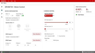
The GUI is configured for the 390 ohm resistors. Is there something I am missing that is causing such an error to be reported on this screen? It also seems to “latch” at a specific value, is there a sampling/refresh rate that the GUI updates these values at as well as the resolution on the ADC used here?

2) When I have Open Load Detection Enabled, every time I start the Motor the nFAULT red LED is turned on (and can be cleared when toggle the Sleep input via the Wake Slider). When I disable the Open Load detection the nFAULT is never tripped. I am confused as to how this is happening. If it is the Open Load Detection that is tripping the nFAULT, it looks like it is only checked in the HW version on start-up or coming out of sleep mode per the datasheet and the error is still occuring otherwise. 

Any help is greatly appreciated!

John

  • John,

    For #1, I believe this is a peak value and that is why it appears to "latch".  This might be the start-up current for the motor and the reason it is higher.  Is it possible to get scope captures of iPropi and a current probe on the motor on start-up?  This should confirm my suspicions or further point to the GUI as the problem.

    For #2, open-load ACTIVE is also enabled on the DRV8873H.  Please find the following section in the datasheet.

    In the hardware version of the device, OLA mode is active when the nOL pin is left as a no-connect pin or tied to ground. If low-side current recirculation is done with independent PWM control, an open load condition is detected even though the load is connected. To avoid this false trip, the OLD must be disabled by taking the nOL pin high; however, both OLA and OLP diagnostics will be disabled.

    OLA can be finicky and there is a warning in the datasheet just above this statement.  

    Regards,

    Ryan

  • Thanks Ryan!

    Let me follow up with the engineer and get back to you. I will close this if there are no follow ups!

    John

  • Thanks John!

  • Hi Ryan,

    Sending you some waveforms from my customer via email now, follow up question below:

    OLA Detection note we talked about:

    NOTE from Datasheet: The OLA mode is functional only when high-side recirculation of the motor current occurs. Depending on the operation conditions and external circuitry, such as the output capacitors, an open load condition could be indicated even though the load is present. This case might occur, for example, during a direction change or for small load currents with respectively small PWM duty cycles. Therefore, TI recommends evaluating the open load diagnosis only in known, suitable operating conditions and to ignore it otherwise.

    Question:

    If I am reading this note correctly, it would be best practice to disable/ignore during start-up with no load conditions of driving the motor if these states do not cause an overshot voltage greater than VOLA­, reset the FAULT or re-enable OLD once motor speed/load has been established? I can also confirm that this OLD Fault is tripped on the DRV8873S eval kit on motor start-up (which I think would be expected).

    Do you agree that is the best method?

    John

  • John,

    Yes, I agree this is the best method.  

    Regards,

    Ryan