This thread has been locked.

If you have a related question, please click the "Ask a related question" button in the top right corner. The newly created question will be automatically linked to this question.

DRV8353RH-EVM: Motor Characterization and potential failure

Part Number: DRV8353RH-EVM
Other Parts Discussed in Thread: DRV8353
  1. It seems the PC tool DRV8353Rx has some auto motor characterize feature, but it is not clear how to use it, do you know where I can find instructions on that so the motor characteristics are measured? And I see no option to use hall sensors, do you know how I should select that.
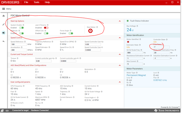
    1. It also seems the user.h file is very important, but I don’t really understand it’s role, or how it is set up, I can’t find instructions for that.
  2. Do you know if this eval board is prone to failure, sounds like the gate driver in particular may fail easily?
    1. I have 48V 2A supply connected to it and a pretty beefy BLDC motor that I had lying around until our actual motors arrive, and I was clicking around the PC tool and it seemed to start some auto motor characterization routine. The motor never spun really, just shook around a little, I don’t believe it was trying to use the hall sensors, and I haven’t shorted R48, R50, and R52 yet, so the hall sensors were not available. After that routine stopped I tried to command the motor to spin and it just jumped a little and now the fault LED turns on (PC Tool indicates GDF, gate drive fault) and the motor does not move at all. I believe something on the board burned out.

I have a second board, but doing some research on the forums it seems like this board might fry easily? A lot of threads mentioned the current limit defaults to the maximum and the board can burn itself out? But I see there is a fuse on the board, so I wouldn’t think it should be able to do that, but it seems a lot of people are having this problem anyway.  So I want to make sure I am doing the right sequence. It seems for the motor profiler I need to configure multiple things and I am not sure what to do with the information after it is done, does it get saved to user.h automatically when it is done?

  • Hi Nicholas,

    Thanks for your question! The team will get a response out to you before the end of Thursday.

    Thanks,

    Matt

  • Hi Nicholas,

    The GUI uses sensorless FOC: it doesn’t support sensored commutation. The motor identification feature that you mentioned is inherent to the source firmware used called InstaSPIN-FOC. This feature automatically identifies the motor parameters buy running the firmware and it automatically measures the motor characteristics. The firmware is available on the product tool page, and you can either talk to the C2000 team or view the InstaSPIN-FOC User Guide for more information (including how user.h works).

    In order to use the GUI and EVM, I would highly recommend reading through the EVM User’s Guide and Software User’s Guide to begin with to understand the hardware and firmware used for this GUI. Typically, customers burn their driver or FETs by applying too high of a gate drive setting (IDRIVE), but in this GUI, the IDRIVE values are fixed (150mA/300mA), so this is likely not the issue. I expect that the motor may not be configured correctly with the algorithm such as number of pole pairs, startup estimation current, etc.

    You can find the InstaSPIN-FOC User guide under “Technical documentation” on the following webpage: https://www.ti.com/tool/DRV8353RH-EVM

    If you have more specified questions, continue to let us know and we will help

    Best,

    Johnny

  • Hi Johnny,

    I tried the second board we have and I did have the number of poles set to 4 before, the motor actually has 7.

    I set it to 7 and ran the motor parameter detector again, settings below is what I used. Based on the user manual this is how you get it to detect electrical characteristics of motor, enable RsRecalc, Offset Calc, and Force Angle, then Start Motor.

    It ran the routine once, motor jogged a little, never rotated more than a few degrees but it completed without error. Ran it again, after a few seconds it made the same tapping noise that the other board made, now the fault LED turns on as soon as I tell it to do anything, and fault indicates Gate Dive Fault. I believe this board destroyed itself too.

    I am not sure what is so sensitive about this design, maybe it is the motor I am using. I would expect the board to limit whatever it tries to do to protect itself. I used this motor with fairly low power ST motor dev kit and it was able to characterize and run it fine, so it is not a totally abnormal motor for this sized driver.

    Do you know of any other TI drivers which are about the right size for us? We are looking for approx. 48V, 600 to 1000W, FOC BLDC control.

  • Nicholas,

    Thank you for the follow up! I will make sure to look into this information and get back to you by the end of tomorrow.

    Best,

    Johnny

  • Nicholas,

    Firstly, to determine whether the driver is broken, unplug the USB, unpower the board, repower the board, and plug the USB back in. Then check to see if the fault LED is still on. If the nFAULT LED does not turn on, this indicates that the DRV8353 is still functional. Make sure that you can enable the device using “System Enable” in the GUI and a fault does not still appear.

    Regarding what occurred: It is likely that the motor parameters were not identified correctly. If the motor resistance (Rs) and inductance (Ls) are too small, the motor may only spin a few degrees or shake in place (‘jogging’ or ‘tapping’ would not be out of the ordinary). The main cause of this is the Resistance and Inductance estimation current is too small or the motor poles is incorrect. If there is not enough resistance estimation current, the algorithm will underestimate the resistance of the motor and this will underestimate the inductance of the motor.

    If the device(s) still work, could you increase your Resistance estimation current and Induction estimation current to a higher values and see if the motor spins during the identification period? (i.e. 3A to 4A for resistance estimation current, and -3A to -4A for inductance estimation current)

    The DRV8353 option is the best recommendation for the gate driver as it is 100-V rated and suitable for the motor application. Will the customer be creating their own FOC code and are just using the DRV8353EVM GUI for FOC evaluation?

    Thanks,

    Johnny

  • Hi Nicholas,

    Do you need any further assistance on this thread?

    Thanks,

    Matt