This thread has been locked.

If you have a related question, please click the "Ask a related question" button in the top right corner. The newly created question will be automatically linked to this question.

DRV8343-Q1: The driver chip falsely reports SHT_BAT or SHT_GND failure

Part Number: DRV8343-Q1

Hi Team,

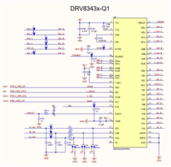
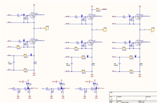
Application: The DRV8343S driver chip is used for the motor control of the 24V automotive electronic water pump. The schematic diagram is as follows.

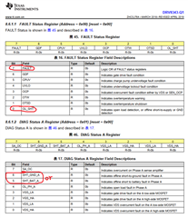
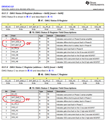
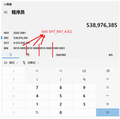
Before PWM starts, send the open circuit or short circuit protection detection enable bit to the DRV8343S chip through SPI. The driver chip will occasionally report a short circuit to the power supply (SHT_BAT) or a short circuit to GND (SHT_GND).

In the standby mode, write parameters to the register via SPI:

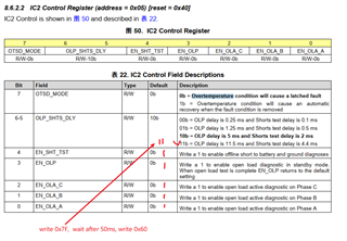
Send 0x7F to the IC2 register, wait for 50ms, and send 0x60 to the IC2 register; a false alarm will occur.

Question:

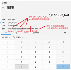
1. IC2 register, can both short-circuit detection and open-circuit detection be enabled at the same time? That is to write 0x7F, bit3 EN_OLP and bit4 EN_SHT_TST write 1 at the same time?

2. How to choose bit6-5 OLP_SHTS_DLY in IC2 register? Is the delay value: the larger the value, the less likely it is to falsely report the fault? Currently 11b is used, and the fault will be falsely reported when only 10b is used before.

3. In the IC2 register, when bit4 EN_SHT_TST is written to 1, is it required that the motor is completely stationary, or what is the minimum speed (electrical frequency) limit?

4. In the IC2 register, when bit4 EN_SHT_TST is written as 1, is there any requirement for the ambient temperature range? Can the whole temperature range of -40℃~125℃ be detected?

  • Hi Annie,

    This will take an additional day to review. I look forward to getting you an answer tomorrow afternoon.

    Thanks,

    Michael

  • Hi Annie,

    Thanks for the detailed questions, I hope I can provide some clarity. 

    1. 

    I don’t see an issue enabling both of these detection features, they both have their own independent registers. When OLD get’s detected (load is disconnected from device), the fault, OL_SHT and OL_PH_X get latched high. When open load condition is removed, the MCU can clear the fault with CLR_FLT bit or an ENABLE reset pulse.

    When EN_SHT_TST is set high, all the current sources on DLx are enabled. If the voltage across any of the current sources exceed Vth, then nFAULT will be driven low. OL_SHT and SHT_BAT_x bits will be set after this happens.

    So, to answer your question, can you have both set at once? Yes, you can, but if a fault occurs then you would have to check the bits on SHT_BAT_x and OL_PH_x to see what caused the fault.

    2. If you are seeing faults happen at 10b then I would suggest using 11b since it has over twice the OLP delay. When using 10b, how often are you getting faults compared to 11b?

    3. The motor needs to be completely stationary (no commutation). 

    4. The function will work across the entire operating temperature range of the device, however the actual voltage thresholds for detection may shift.

    Please let me know if you have any follow up questions.

    Regards,

    Michael

  • Hi Michael,

    thanks for your response.

    1. Compared with 10b and 11b, the frequency of false alarms is almost the same.

    At the beginning, the 10b configuration was used. When a fault is falsely reported, A, B, and C of SHT_BAT_x will appear at the same time;

    Later, it was changed to the configuration of 11b. When the fault was falsely reported, SHT_BAT_x, sometimes ABC appeared at the same time, and sometimes only AB, or BC, or CA appeared;

    2. When short-circuit detection is enabled, the power supply at both ends of the current source exceeding Vth will trigger a fault. The value of Vth seems to be unable to be modified through the register.

    How much V is Vth here? Not seen in the technical manual;

    3. If the capacitance value of the three-phase wire of the motor to the positive or negative pole of the DC bus is large, can it also cause a false short-circuit fault report? How much can the capacitance value not exceed? When the short circuit is detected, the current source inside the DRV8343 will be activated. What is the current output of this current source? 

    Later, another circuit board was tested (the same: circuit board + motor + software + experimental environment + test method), and it was tested continuously for about 7000 times, and there was no false alarm. It can be basically determined that the previous false alarm is not caused by DRV8343, but the specific cause cannot be confirmed.

    Thanks,

    Annie

  • Hi Annie,

    Michael will get back to you before the end of the day tomorrow.

    Thanks,

    Matt

  • Hi Annie,

    Vth is dependent on the FET you’re using, it’s the threshold of the FET. Vth is the minimum gate to source voltage that is needed to create a conducting path between source and drain. This is listed on the datasheet and for this FET the min Vgs is 1.2V.

    For the new board that you’re testing, what bit setting are you using for OLP_SHTS_DLY?

    Maybe there was some sort of ESD damage on the first board?

    I’m not sure what you mean on #3. If the motor phase is highly capacitive relative to the power supply or GND? The motor phases are inductive, not capacitive.

    Please let me know if you have further questions.

    Thanks,

    Michael

  • Hi Annie,

    Do you need any more help on this thread?

    Thanks,

    Matt