This thread has been locked.

If you have a related question, please click the "Ask a related question" button in the top right corner. The newly created question will be automatically linked to this question.

DRV8825: DRV8825PWP lose steps

Part Number: DRV8825
Other Parts Discussed in Thread: DRV8711

After Service Ticket no.: Number: CS0554686

Hello,

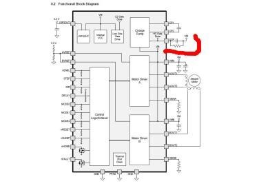
  WE got a very strange and thorny phenonmenon with DRV8825 driving stepping motor.

  1. Phenonmenon 

  •      The motor loses steps after continous running on a product in mass production 
  •      Failure rate: 20% with the same batch of DRV8825
  •      Experiments did to try different batches of DRV8825, the failure gone or down to very low failure rate 
  •      Max. step lose: 100 full steps in 48 hours (continous running)

  2.  Working conditions
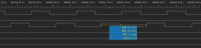
  •       Speed: 750rpm
  •       Decay mode: fast
  •       Peak phase Current: 1.2A
  •       Micro-stepping: 1/8

   3.  Experiments did

  •    Tried different baches of DRV8825:
    • the high failure rate batches: 05TG5AV7T, 06TG5A1JL,0CTG5CCRC .
    • low failure rate (or woking well) batches:12TG5 AXC7
  •    Swaped the different batches of DRV8825 on the same PCBA board, good batch still good, and "bad" batch still does not work.
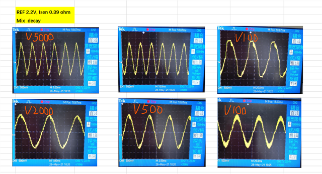
  •   We tried the mix decay mode, the failure rate sharply reduced, still monitor it.  

It is quite urgent and as the mass product is down. Please help look at it and looking forward to your any suggestion or feedback. So appreciated!

  • Jian,

    Please change the STEP pulse waveform to keep STEP high (twh(step) parameter) longer than 4.6us to make sure STEP signal can be received.

    Regards,
    Wang Li

  • Hi Wang,

      Thanks for the quick response.

      The datasheet specify the twh > 1.9us, why should be >4.6us?  Any restriction?

      Best Regards

      Jian

  • Hi Wang,

        1. We measured the STEP high, it is around 20us and in the specification. Please refer to the figure below. Please advise.

        2. Meanwhile, we found the latest datasheet recommend a resistor paralled on hte PIN VCP, while not in the old verison. Is that a must?


    Thanks!

  • Jian,

    1. The 20us STEP high can remove the minimum twh concern. BTW, we are in process to update twh in datasheet.

    2. The extra 1Mohm can quickly discharge the charge pump voltage in sleep mode to keep the high side FET off in sleep mode. I would add it if re-spin the design.

    3. Comparing the fast decay and mixed decay waveform, the mixed decay output current ripple is much smaller than the fast decay's. For the same peak current setting, the mixed decay mode has a higher average current which can give a high torque. I think that is the root cause of this issue. In general, a stepper motor would reserve enough torque to make sure no skip step. I would recommend increasing the full scale current setting a little bit.

    Regards,

    Wang

  • Hi Wang,

      1. From your experience, what is the actual impact of the ripple on the fast decay?

      2. I do not think the torque is the root cause of the step loosing, as we tried the half current to drive the step motor, it is working well without step missing.

      3. We tried to use 5 WHY to explain and prove the evidence, at least so far we are not fully convinced as some batches of DRV8825 work well as both decay mode, while some work only one mix decay mode. Do you have any other hints to look into it to prove RC and close the loop? Thanks .

      By the way, we tried different batches as mentioned as above, can you identify the manufacturer site and date? As you know, in order to resume the production, we may consider to order the same batch.

     Best Regads

     Jian 

  • Hi Jian,

    I am not going to prove that problem isn't caused by DRV8825 but I have a few thoughts. I think the only current waveform for speed around 750rpm (if you use 1.8deg motors) is V5000 in the third line from the top. The rest is for lower speeds.

    That V5000 waveform looks like triangle what means driver+motor are quite close to mid-range instability area where motor BEMF is similar to VM. The problem might be caused by motors with stronger magnets and higher BEMF or less stiff load.

    If you can try to run driver:

    - at higher VM voltage (10%-20%) and check if it helps,

    - in full step mode for 750rpm and check if it helps.

    I would also check if load is the same as before (ie. no loose toothed belt for example).

    Regards,

    Grzegorz

  • Jian,

    1. Fast decay has a higher ripple current and lower average coil current (less torque).

    2. "tried the half current to drive the step motor, it is working well without step missing." Do you keep the same input voltage and run at same speed when run the half current?

    3.  How do you define "missing step"? Would you show the waveform with "missing step"? I want to check the waveform follows sinusoidal waveform or not?

    Thanks,

    Wang

  • Hi Wang,

    Q2:  Just lowered the VREF to reduce the phase current, kept other parameters as was, the "good batch" still works, while "questioned" still does not work, interesting.

    Q3:  We do not have the appropriate test gear to capture the waveform while loosing step, as most of the failures incurred after 10 hours running, do you have any recommended tools to measure? I are eager the tool as well.

    By the way, we tried V400 (60rpm) with fast decay, the motor still lost steps, headache. I ever used the DRV8711 which can set the percent of the decay, seems DRV8825 does not support this feature?

    Thanks!

    Jian

  • Hello Gregorz, 

       Thanks for reply. This is really a headache issue I ever met, tried all the ideas I have.

       The VM is 24V DC and we are doing experiements to look for the best parameters by adjusting  VREF and isens resistor, meeting all wide speed range from V5000 to V20 with single decay mode.

        Do you have any other suggestion? 

        Thanks

        Jian


  • Hi Jian,

    If you need some range of speeds I would change slowly speed from minimum to maximum and look for any resonances (noises). If there are any speeds that cause resonance I would try either avoid these speeds or try to reduce the resonances.

    If motor changes its direction I would check if DIR signal meets its timing requirements (Figure 1. Timing Diagram), I would also check if DIR/STEP signals are clean.

    If motor changes its speed and/or direction I would check how current looks like during acceleration/deceleration and/or direction change. I would also try to change acc/dec ratio and check if it helps.

    If motor current is turned off from time to time I would wait 50-100ms after turning current back on before proceeding with step signal.

    Regards,

    Grzegorz

  • Jian,

    "the failures incurred after 10 hours running"

    Would you monitor STEP signal and the output current on the scope and share it to here? I am trying to understand the root cause of loosing step:

    a. Does the indexer table move to the next step setting with one STEP pulse?

    b. If the output current follows the indexer table, does "loosing step" mean the motor doesn't move even the output current follows the indexer table?

    Regards,

    Wang Li

  • Hi Wang,

       Thanks for the consistant support.

       Luckly we captured the waveform while loosing steps,  as below. Please help review and guide how the phase waveform come from.

       Note that: all the abnormal waveform was captured from the "bad batches" DRV8825 with FAST DECAY. 

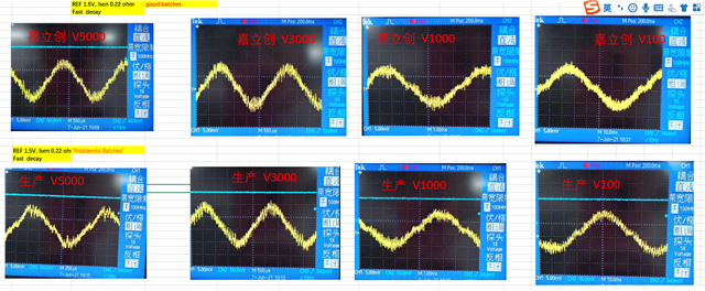
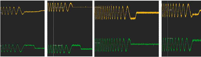
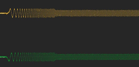
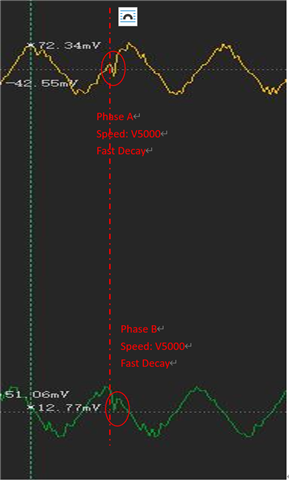
        could not undersatnd, why there is current drops on the phase A and B with FAST DECAY.  


    could not understand why the phases are not  synchronous and finally went to ZERO current?

    Thanks in advance!

     Jian

  • Hi Grzegorz,

      Please kindly look at the acceleration/deceleration waves as blow, it looks good.

     I uploaded anothers 2 abnormal phase current wave in the following replies, please help analysis as well. Thanks!

     Jian

  • Hi Jian,

    The last waveforms look OK but drop in current during accelaration means that drive + motor operate in the region of mid-range instability area which may be tricky. I explained that in my first post.

    In case of first waveforms at V5000, not stable current might be a sign of resonance in mid-range instability area. I can not tell why some of DRV8825s may show that symptom and other not.

    To analyze what is going on with 4 waveforms in deceleration phase we would need to know how STEP, VREF and nFAULT signals look like and maybe also other signals like DIR, nRESET, nENBL and nSLEEP.

    Regards,

    Grzegorz

  • Jian,

    According to the current with "missing step", the motor is running in speed mode (not count how many steps). In that speed mode, the back EMF is higher enough to make the output current doesn't follow the sinusoidal waveform. It could also cause the current glitch with motor vibration or load torque spike.

    From the waveform, I cannot tell  the indexer table moving to the next step setting or not with one STEP pulse. 

    Can we slow down the motor and monitor the STEP pulse while monitor the output A and B current? BTW, when we say miss step, it means the output current doesn't change with a step pulse. If the current changes, I cannot say the motor driver misses steps.

    "bad batch" Do you mean only this batch DRV8825 samples have this issue? How many do you build before and this batch? How many samples have this issue?

    Regards,

    Wang