This thread has been locked.

If you have a related question, please click the "Ask a related question" button in the top right corner. The newly created question will be automatically linked to this question.

DRV8876: Unexpected current peak when braking DRV8876

Part Number: DRV8876

Hi everyone, 

I'm using the DRV8876 motor driver configured in PH/EN mode and without using PWM control input.

I am seeing an unexpected current peak at the output of the Ipropi pin each time I perform a brake (slow decay) to the motor.

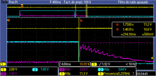
Here is the capture with the oscilloscope:

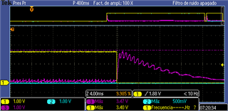
The yellow corresponds to PH/EN input, the blue signal corresponds to PH/IN2 and the magenta is the Ipropi output.

The Rpropi resistor has a value of 1KOhm, therefore the relationship between the motor current and the sensed current is 1:1.

What could be the reason of having a 3A peak current when I perform a brake?

Thanks in advance

  • Hi Gorka,

    • Can you take another scope image showing the VM supply voltage, output voltage and IPROPI?

    Normally, when the H-bridge enters brake mode after its driving phase, the top FET is disabled and the bottom is enabled. When this occurs, there is sudden change in output voltage which can generate some oscillations and spikes in the output current. I wonder if this is what is happening in your board. The waveform I asked you to take will help me understand if this is the case.

  • Hi Pablo, 

    Thanks for your response.

    I hope the following screenshots will help in trying to understand the problem. 

    In the following image, the yellow signal is Vm, the blue signal is EN/PH1 ctrl signal and the magenta is the current from Ipropi:

    In the following image, the blue and yellow signals represents the motor outputs OUT1 and OUT2:

    I have realized that even the driver is current limited to 2,5Amps, this overshoot goes to 3,4Amps.

    Thanks in advance,

  • Hi Gorka,

    I took my own waveforms using the DRV8876 evaluation boards and a motor. As you can see on the waveform below, during Brake decay, the current should go to zero during the dead time (t_dead) which is the time where all of the FETs are disabled before enabling the LOW side FETs to prevent both FETs of the half-bridge from being enabled at the same time. However, the IPROPI voltage value should go up to nominal value after dead time (t_dead) expires and the LOW side FETs are enabled. Then as the EN goes back HIGH, IPROPI voltage will increase as current starts increasing in the motor windings.

    I'm puzzled as to why your waveform is abnormal. Can you share your driver circuit schematic? I want to learn how you have configured IPROPI. You can send me a private message if you don't want to share the circuit in the public forum.