This thread has been locked.

If you have a related question, please click the "Ask a related question" button in the top right corner. The newly created question will be automatically linked to this question.

DRV8320R: Motor driver gets destroyed when VM applied

Part Number: DRV8320R
Other Parts Discussed in Thread: DRV8320, DRV832X

Hi,

I have a strange behaviour with my new PCB design, which worked very well in the old design.

The schematics are nearly the same for both layouts, except the new layout uses a new MOSFET and more bulk caps, but

the gate charge and all primary parameters are nearly the same:

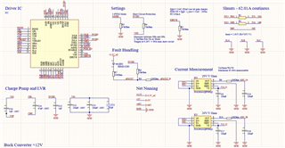
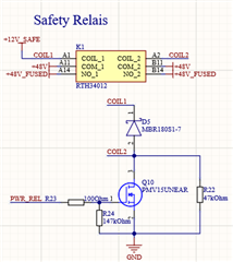
I use a relay to supply the power to the MOSFET stage and this worked very well so far in the old design, when I trigger the relay in the new design,

it destroys the DRV8320 immediately if the supply voltage is above 40VDC (I have 10 boards and I could destroy 8 out of it, surprisingly two work, but the signals to the gates looks pretty bad and at 20A the DRV8320 got a fault). At 20VDC i could not destroy the DRV8320 in the new design. The DRV8320 is destroyed also, when I disable the enable pin, so this seems not to be a problem with the gate drive layout, which is worse in the new design, i know that and I will fix it in the next iteration. I also desoldered the CPL/CPH and VCP cap to ensure, that there is not a shorted capacitor responsible for the problem.

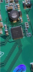
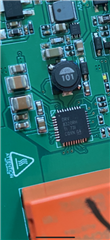
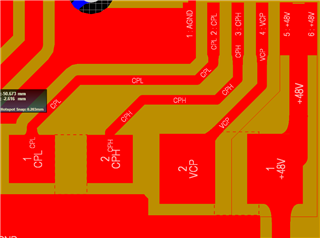
When the relay closes, it sparkels a little bit at the DRV8320 and then the driver is shorted internally, which means VM, DVDD, CPL, CPH, SHx, GHx, GLx are shorted together. I cannot see any significant overshoot at the VM pin. I let everything assemble in China and the same manufacturer made both PCBs and I also checked all the components with the schematics, this should be fine. The DRV8320 on the new board have some different number, so I'm not 100% sure if this is not a fake product, so here is a photo, maybe you can verify:

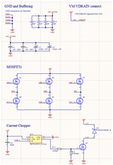
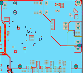
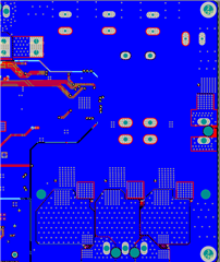
The old (working) layout looks like this (On top it looks like CPL und CPH are shorted, but this is a polygon cutout and it is only depicted so if scrolled out too much):

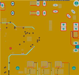
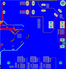
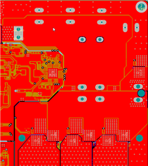
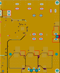
The new (not working) layout like this:

I really don't know what could cause this problem, I would understand it, if it would happen under load, but this is under no load (no motor is connected).

Edit: Something that also might be important is, that the new design is 1oz/2oz and the old design was 0.5oz/1oz for the inner/outer layers

  • Hi Sebastian,

    I submitted your picture to see if we can get traceability on that unit.

    In the meantime can you provide capacitor voltage ratings for C15 and C11?

    What were the few schematic changes made between the old and new rev?

    Thanks,

    Matt

  • Hi Matt, thank you.

    C15 has a raiting of 10VDC, C11 has a raiting of 75VDC.

    None of the capacitors was shorted after desoldering, so the raitings should be fullfiled.

    I had now a look at everything, but I couldnt find anything. The only change is additional bulk caps of 2x470uF,

    1x10uF additional X5R and I changed from BSC0702LSATMA1 to BSC040N08NS5ATMA1 MOSFETs

    I further made now a voltage test with the critical caps around the DRV8320 and the raitings seems fullfield.

    Kind Regards,

    Sebastian

  • Hi Sebastian,

    FYI - the part image shows a lot trace code which was manufactured way back in March 2017. So it seems to be a little bit old. We have seen some cases where brokers are mishandling devices and that results in damage. However, I can't say that is the case for you.

    Thanks,

    Matt

  • Hi Matt,

    Ok, that parts seems pretty old, so the chances are high when stored wrong that it has to do with humidity.

    Do you know, if humidity damage could cause such behaviour, that for example the maximum voltage rating decreases?

    It could also fit, since only 8 out of 10 have that issue.

    Here is the DRV8320 from the working board, can you tell me what's the manufacturing date of this one (TI 93I G1YG G4 I think)?

    Kind Regards,

    Sebastian

  • Hi Sebastian,

    That last part was made in March 2019.

    Thanks,

    Matt

  • I have 3 more new boards, that should work and I can experiment with. What would you do to better evaluate the error?

    I tought about this: Shorting the relay and start at 15VDC, measuring VCP, VM, DVDD and +12VDC with an oscilloscope and slowly increase the voltage to 40VDC. The problem is, I cannot set a valid trigger but I think anyway if this fails, some components voltage raiting is too low.

    Then I could do the same, but this time the relay triggers and I can measure any possible overshoot on VM, VCP, DVDD and +12VDC, but I don't expect this to happen.

    What I also tought about is, that 2Oz copper leads to worse soldering and so it might be, that the clearance is worse on this board, maybe that could be a reason for the short. After the shorting, the following Pins have a connection to GND: 

    CPL, VM (not on all), CPH, VCP, nFAULT, DVDD, SHx, GHx

  • Ok Matt, I could capture the problem:

    This is VM when the relay triggers. Through the better design and more caps, a much larger current can flow to the VM caps and through the parasitic inductance, a large overshoot is triggered. When I bridged the relay in a first case, I got no problem at all. So, in the old layout there was less bulk caps and less bypass caps, so that was not a big deal there. Or might this overshoot even come from the relay bouncing?

    What I don't fully understand is the gap of around 500us, is this from the bouncing?

    On the old board, I have only one trigger and there is no overshoot at all, so I find this kind of strange, since the output load is the same. Could it be, that a bad soldering of the relay because of 2Oz copper could be a reason?

  • Hi Sebastian,

    That voltage overshoot looks quite dangerous. If you zoom in even further on the timescale you might observe the voltage exceeding 65V!

    It could be that you are building up a very large current in the relay (supported by the bulk capacitors) and when it bounces you are causing sparking to occur from the large negative or positive voltage from the inductance.

    If you add a diode from GND to the DRV side of the relay, that would help.

    I'm willing to bet the gap you see is due to the bouncing. Can you drive the relay with less current, maybe by putting a resistor in series? That may cause it to bounce less and make better contact.

    Bear in mind a very quick rise time in voltage at the DRV832x can potentially trigger the ESD structures to latch. It may be better to have the capacitors on the DRV side rather than before the relay.

    Thanks,

    Matt