This thread has been locked.

If you have a related question, please click the "Ask a related question" button in the top right corner. The newly created question will be automatically linked to this question.

DRV8412: Decaying sinusoidal oscillations on the driver OUT A pin

Part Number: DRV8412

Hello,

I am using DRV8412 in full bridge configuration to run a Brushless DC Servo motor. I am getting whining sound from the inductors on the three phases. The whining sound does not occur in any set pattern and when it does, the noise is consistent when the system is idle and the it occurs intermittently when the system is in use. I am including schematic snippet. The voltage test points are highlighted in red and the current direction through the inductors is highlighted in green

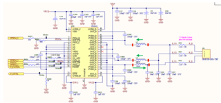
The input PWM to the driver is fed by an NI - SOM. I only have access to components starting from the inductors on the Driver Out line for probing because of the way the components have been mounted. I have measured the current and the voltage waveforms during the whining noise highlighted in the schematic. I see dying sinusoidal oscillations on the PWM resembling the natural response of an RLC circuit.

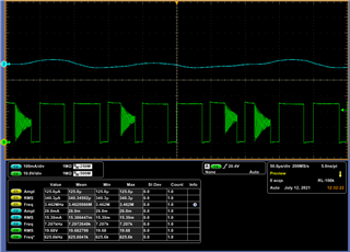
Phase A current and PWM (Before Ind)                                       Phase A current and voltage (After Ind)                  


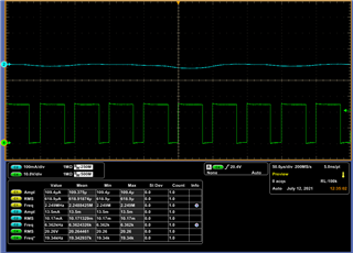
Phase B current and PWM (Before Ind)                                       Phase B current and voltage (After Ind)


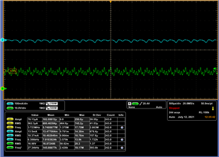
Phase C current and PWM (Before Ind)                                       Phase C current and voltage (After Ind)


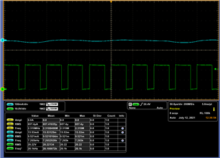
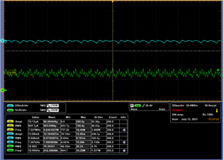
I see pronounced positive peak in the current ripple of Phase A and negative peaks in the Phase B and C. The amplitude values measured in the scope suggest that the current from Phase A is spitting between the Phase B and C (highlighted in the schematic).

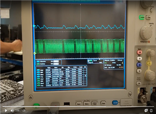
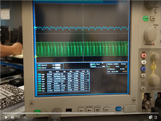
The illustrations below indicate that the whining noise occurs momentarily when the system is in use. Phase A current and PWM (before inductor) shown.


Please let me know to proceed in fixing this. Any help is appreciated.

Thanks ,

Bala.

  • Hi Bala,

    Thank you for posting to the forum.

    Please allow us 24 hours to investigate your problem. Expect a reply within 24 hours.

    Regards,

    Pablo Armet

  • Hi Bala,

    Apologies for late reply.

    Have you tried measuring the outputs without the load? I want to know if the oscillations on the voltage waveforms is due to the PCB layout or if it comes from the load. Can you remove the load and capture the output voltage waveforms.

    Another test you can do is to drive a different load like a resistor or a brushed DC motor. Is the noise problem still present?

  • Thank you for the response. I will try to capture the voltage waveforms without the load and with different loads and get back to you soon.

  • Hi Bala,

    What was the operating difference between the last two waveforms? I saw the phase A current waveform is different between them. Which one had the noise? 

    How many us/div are in the last two waveforms. 

    To avoid the audible noise, we want to see the PWM frequency higher than 20kHz. To have a small output current, the high side FET turn-on time could be small. But, DRV8412's Minimum PWM pulse duration, tON_MIN, is 50ns. We need to make sure the output current is higher enough to make sure the PWM pulse duration higher than 50ns.

    Regards,

    Wang 

  • Hi Wang,

    The motor is being used to rotate a prism in rapid sequence that ultimately guides a laser beam. So during the operation of the motor, the whining noise occurred only for a few moments. I had captured the last two waveform for that occurrence in 500 us/div. Also the PWM frequency is set to 20 kHz and I am pretty sure the pulse width is much higher than 50ns. Any hypothesis is welcome.

    Regards,

    Bala

  • Hi All,

    Just a few thoughts.

    - resonant frequency of output filter is  f = 1 / (2π √L C) =  1 / (2π √150x10^-6x10x10^-6) = 4.1kHz, frequency of phase A voltage oscillations after inductor is around 5.8kHz, not exactly the same but quite close, maybe those oscillations at 5.8kHz are caused by output filter resonance

    - voltage amplitude of those oscillations after inductor is around 5V, impedance of output capacitor (10uF) for 5.8kHz is 2.8Ohm so amplitude of current flowing through that capacitor is around 1.8A (that current is a sum of inductor current and motor current). OC threshold is 1.4A so H-bridge may go into Hi-Z mode when inductor current reaches 1.4A. 

    - high frequency oscillations at phase A before inductor are not limited by VDD or GND so H-bridge is probably in Hi-Z mode. Every PWM cycle with oscillations starts at a bit higher voltage than others so it looks like current is flowing into phase A increasing its voltage over VDD by HS mosfet body diode voltage drop and at the same time H-bridge A is in Hi-Z mode.

    I think it would be useful to measure phase A inductor current instead of output current, it could prove output filter resonance theory.

    Maybe placing series resistor 1-5 Ohm with 10uF output caps or changing PWM frequency could prevent those oscillations.

    Regards,

    Grzegorz

  • Thank you so much for your response. Let me get back to you if this works.