This thread has been locked.

If you have a related question, please click the "Ask a related question" button in the top right corner. The newly created question will be automatically linked to this question.

DRV8350H-EVM: How to control output current

Part Number: DRV8350H-EVM
Other Parts Discussed in Thread: DRV8350

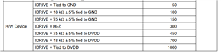
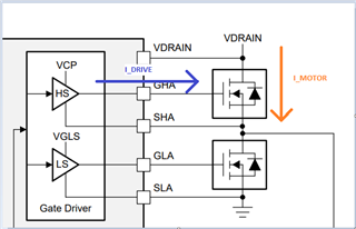
I'm trying to use this evaluation board to run a motor, and I want to limit the motor I'm using to draw less than 1.5 A. From reading the ICs datasheet, there seems to be a way to do so with changing the resistor value for IDrive. I've tried changing the resistor value to different values in the datasheet, but it doesn't make a difference. The settings in the software for the Eval board don't seem change anything, and I have it set to the lowest motor speed setting as well. Is there a way to control the output current that the Motor draws?

  • Hi Joseph,

    Thanks for posting your question to the forum - 

    We are looking into this and will reply shortly 

    Best Regards,
    Andrew

  • Hi Joseph,

    Thanks for your patience - please see below responses and requests for more information.

    We are also still looking into this e2e thread and will try to propose some more solutions for controlling motor current.


    Response to your questions:

    1. To clarify, the IDRIVE current is different than the motor output phase current
      1. IDRIVE is between the gate driver and the output power FET gate
      2. I_MOTOR is between the output power FET drain and source
      3. Please refer to the diagram below, and I have also attached some resources on IDRIVE that might be helpful
    1. Noted that you are trying to reduce I_MOTOR output phase current to be less than 1.5A
      1. Because the resistor setting you mentioned is specifically for IDRIVE, it will not have the desired effect you are expecting on I_MOTOR
      2. Instead, motor phase current can be controlled by updating your commutation settings in the GUI
        1. Reducing the speed should help reduce the motor phase current as mentioned.
        2. The motor's physical design (resistance of windings) also has an impact on the current being drawn

     Requesting more Information:

    • What motor phase current levels were you able to measure, for each speed setting attempted?
    • Can you please share some more information on the circumstances of high current being observed?
      • Example: Is this during initial motor start-up, or during steady state motor operation?

     Diagram

    • On the left is the DRV8350 gate driver, which provides I_DRIVE current to the external FETs
    • On the right is the external power FET that turns on/off and allows motor phase current to flow between Vdrain and SHx


    Thanks and Best Regards,

    Andrew

  • Hi Andrew!

    Thanks for clarifying which current I_drive is. I think the high current draw is really just the initial startup current, as it settles at a current less than the rated current, so I think that issue is resolved. I also wanted to ask if there was a document on what each parameter for the GUI? The motor we're using is rated for 42000 rpm, but when I try to increase the speed, the motor shuts off and a red LED turns on on the Eval board. After playing around with some of the parameters, I've noticed that other parameters I thought had nothing to do with increasing the motor speed actually helped. The max rpm I've been able to get so far is around 6000 rpm, which isn't anywhere near what its rated for, so I was wondering if there was a thorough document for what each parameter does

  • Hi Joseph, 

    Thanks for the update and info. Please see responses from me below: 

    1. For GUI parameter info,
      1. Please refer to technical doc tab of the EVM on the TI website here: https://www.ti.com/tool/DRV8350H-EVM#tech-docs
        1. There are software guides (sensored and sensorless versions), and a guide for the EVM hardware itself 
    1. From the information you provided about motor speed debug,
      1. We noticed that 42000 rpm is a very high motor speed, and the default GUI software might not be able to support that high of a speed setting
      2. Also, one important note is that the Red LED turning on past 6000 RPM indicates a FAULT condition
        1. In the datasheet, there is some info explaining the different fault conditions possible
        2. Link: DRV835x 100-V Three-Phase Smart Gate Driver datasheet (Rev. A)
          Try starting at section '8.3.6 Gate Driver Protective Circuits' on page 50
        3. Since you have a DRV8350H version part and EVM, more info will be needed to identify the exact fault condition that occurs past 6k RPM
        4. Our guess is probably overcurrent protection or over-temperature fault from excessive motor load

    Best Regards,
    Andrew

  • Hello Joseph,

    Do you have any other questions on this thread?

    Thanks,

    Matt

  • Hi Joseph,

    I'll go ahead and close this thread. If you have further questions, please click the "Ask a related question: button at the top right of the window!

    Thanks,

    Matt