This thread has been locked.

If you have a related question, please click the "Ask a related question" button in the top right corner. The newly created question will be automatically linked to this question.

DRV8353R: The influence of IDRIVE parameters on motor control performance

Part Number: DRV8353R

Hi Team,

Customer has following question need your help:

1. When the motor is running in the state of a given desired high torque, if the given desired torque value is suddenly reduced to 0, the motor will suddenly increase its speed and then slowly stop. Why does the motor speed suddenly increase when the current is expected to decrease? Is it related to field weakening?

The following are some data waveform diagrams of test samples:

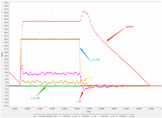
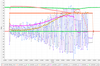
(The above figure is the current sampling and speed sampling curve in the torque loop test. It can be seen that when the expected value of the q-axis current suddenly drops to 0, the speed will rise for a period of time)

2. In the above-mentioned motor debugging environment, the MOS tube drive current setting value of the chip IDRIVE is changed through SPI, from 1000mA/2000mA to 60mA/120mA (the latter is closer to the most suitable parameter value of the MOS tube) . 

The phenomenon of speed increase will change, and the time for the speed spike will be significantly shorter. What caused this change?

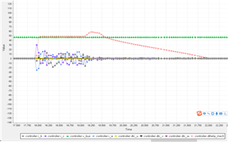
I_DRIVEP=1000mA,I_DRIVEN=2000mA

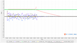
I_DRIVE=60mA,I_DRIVEN=120mA

(The pink curves in the above two figures are the actual speed of the motor feedback. It can be seen that the acceleration time in the figure below is obviously shorter, but the amplitude seems to be larger)

Thanks,

Annie

  • Hello Annie,

    Can you have the customer check the VDRAIN voltage during this test to see if the VDRAIN voltage changes when they change the torque to 0? Typically during a speed change event the motor will act as a generator and cause the power supply voltage to rise suddenly. Bases on the plots it looks like there is not any change but I want to confirm.

    Is this FOC control? In an FOC control algorithm there will be an Iq and Id control loop implemented in the MCU. Rapidly changing these inputs may result in a speed command (PWM duty cycle) overshoot if the kp and ki parameters result in a controller that is underdamped.

    The IDRIVE effects the rise and fall times of the MOSFETs. When you have a lower IDRIVE you are reducing the gate drive current and adding additional delay into the time to turn ON or OFF the MOSFET gates.

    Thanks,

    Matt

  • Hi Matt,

    Thanks for your answer.

    The voltage at the vbus terminal of the sampled motor is the same as that of VDRAIN. According to the curve analysis, the voltage seems to drop slightly (about 3V) when the speed changes suddenly (the acceleration phase before the motor starts and stops). 

    (This graph is the process curve of torque control, the load increases from 0 until the motor is locked. It can be seen that the speed will accelerate for a period of time before the lock, and then quickly decrease to 0 to enter the locked-rotor state)

    Yes, this is FOC control. Modifying the pi parameter of the current loop during torque control does have an impact on the curve. But the customer's doubt is why the speed will increase during the decline process? The closed loop is a pure torque loop, that is, only the current loop is controlled. Is the field weakening phenomenon caused by the overshoot of the Id current when the current is output and the motor accelerates?

    Thanks,

    Annie

  • Hi Annie,

    When you have a sudden decrease in torque, the motor may accelerate due to the motor power being constant. The motor power is equal to VIN * IN or speed * torque. So if the torque suddenly decreases the speed may increase to maintain the same power delivery in the motor.

    Thanks,

    Matt