This thread has been locked.

If you have a related question, please click the "Ask a related question" button in the top right corner. The newly created question will be automatically linked to this question.

DRV8323: The DRV8323 issue for the automated manipulator is abnormal

Part Number: DRV8323
Other Parts Discussed in Thread: DRV832X

Hi 

List the following test items for the DRV8323 broken machine to find the cause of the damage. the total units run are 400pcs and the failed quantity is 12pcs.
Note: All broken devices are manifested as the G pole drive failure of the upper tube, and the waveforms produced by the damaged IC are all in the case of DIS_GDF = 1

1. Compare whether the resistance of the damaged IC pin has changed
Conclusion: Measure the relative resistance of CH, SH; GH, SH to 54V resistance; GH, SH to ground resistance, there is no significant difference

2. Compare whether there is a difference between IC pin and MOS pin waveform
Conclusion 1: Measure the relative resistance of CH, SH; GH, SH to 54V resistance; GH, SH to ground resistance, there is no significant difference
Conclusion 2: There is no significant difference between the waveform of the IC pin and the waveform of the MOS pin
Conclusion 3: The influence of the diode close to the IC and close to the MOS on the driving waveform is the same, the negative differential voltage at the MOS terminal is slightly larger than the negative differential voltage at the IC terminal
Conclusion 4: The GH current of the normal IC is the same as the software setting, the current of the bad IC rises but the voltage is not maintained
Conclusion 5: The VGS of a normal IC will continue to rise with the input power, and the VGS of a damaged IC will not continue to rise when it rises to 6.8V.
Conclusion 6: Diable Gate Drive Fault is to remove the protection, not only does not report an error, changing the T-drive can change the protection time
Conclusion 7: The VCP of the damaged IC has obvious fluctuations when switching, and the normal IC does not
Conclusion 8: Tested 20 different combinations did not work properly

And you can see the schmatic and test report as the following. 

IC波形圖.xlsx

  • Hello Rock,

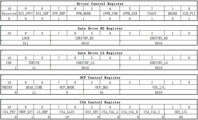
    Can you please let me know what are the device register settings that you set through SPI?

    It looks like your power supply is 54V. This part is only rated for 65V abs max and so you are operating it very close to the limit where it will be damaged. If there are any overvoltage events due to the motor acting as a generator, I would expect the part to be damaged. Sometimes in overvoltage events, the charge pump is damaged first.

    Thanks,

    Matt

  • Hi Matt,

    The SPI is as follows.

    If the damage is the charge pump, does the ABC three phases fail to work normally? We are encountering the situation now that only one of them will report an error: GDF = 1.
    If the error check is disabled: DIS_GDF = 1, the other two phases can normally generate waveforms, and only one phase does not normally work.

  • Hi Rock,


    Please see the below responses:


    Q: If the damage is the charge pump, does the ABC three phases fail to work normally? We are encountering the situation now that only one of them will report an error: GDF = 1. If the error check is disabled: DIS_GDF = 1, the other two phases can normally generate waveforms, and only one phase does not normally work.

    A: Because your fault appears to only be happening on one phase, we think that only one of the gate driver phases in the IC are damaged.


    Damage to the charge pump (VCP) would have an impact on all three phases, as it is used to generate the high-side gate drive voltage for all three phases. Also, it makes sense that an IC with a damaged gate driver phase would have some fluctuations on VCP like mentioned.


    Further debug:

    Would it be possible to capture a voltage waveform of the system's Vdrain?

    It will be helpful to know the max level of the over-voltage generated by the motor, as anything exceeding ~65V can cause damage to the DRV832x gate driver IC.

    We also recommend using a part with a higher voltage rating: DRV8353

    • This would be a pin-to-pin compatible replacement that can handle up to 105V. We typically recommend the IC to be rated >50% higher than the motor's typical operating voltage.
    • https://www.ti.com/product/DRV8353


    Best Regards,

    Andrew

  • Hello Rock,

    Do you have any further questions on this thread?

    Thanks,

    Matt