This thread has been locked.

If you have a related question, please click the "Ask a related question" button in the top right corner. The newly created question will be automatically linked to this question.

DRV110: DRV110 regulation instability

Part Number: DRV110

Hi All!

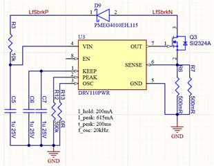
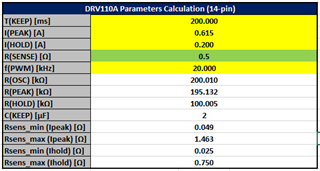
I have recently designed an economizer board for electromechanical brakes on BLDC motors using the DRV110. When testing it I realized that it generates very audible and unpleasant hissing on the brakes although the regulation frequency of 20kHz (0R at Rosc) should be way above my audio range. Except from that the circuit does what it should so I did some investigation.

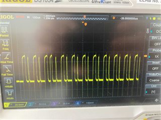
One is that one long pulse is in all configurations I tried (different Rosc, current measurement filters, power supply filter etc) a lot longer than the next one, thus resulting in a "frequency-halfing" effect (see picture from filtered SENSE signal, please excuse the mediocre quality. I suspect that is due to the hysteresis control. Is there anything I can do about it? Supply voltage, brake (and thus inductance) and currents are unfortunately fixed, all suggestions I found so far to suboptimal regulation were changing one of these parameters.

Another thing I realized is that the supply voltage regulation ripple is rather high, even when using massive input filter caps and a series resistor close to the minimum rating. When I supply the IC externally the audible noise gets a lot less unpleasant, so I suspect that the reference voltage is derived from the supply and the ripple induces some interferences. The sound also distinctively changes when adding or removing capacitance. In the datasheet now I found a lot of references to the input zener diode, but on p12 it is a "zener-like" circuit - what is now the real way the input is regulated? Anyway, the result is really not nice, I will add an additional LDO per DRV110, but it would be nice to know whether there is also an easier way.

kind regards,

Tobias Schwering

  • Hi Tobias,

    Appreciate your interest in using DRV110. I am reviewing your concerns and will follow-up with you by end of week. Any chance you could provide a copy of your schematic?

    Thanks,
    Kevin

  • Hi Kevin,

    thanks a lot! Of course, this is the pretty simple basic schematic I used. The top 2 labels are the connections to the Coil, LfSbrkP is supplied by 24V when active. But as I mentioned I fiddled quite a lot with the circuit without anything having an impact on the behaviour I mentioned.

    Kind regards,

    Tobias

  • Thanks Tobias for providing schematic capture. Please give me a moment to respond to your concern buy Wednesday of next week, as I will be out for the remainder of the week.

    Thanks,

    Kevin

  • Hi Tobias,

    To confirm, your primary concern is the noise coming from brakes which the DRV110 is controlling the current supplied?

    I'm curious to see you calculations on how you chose the component values to achieve desired peak, hold, fosc, tpeak values. It surprises me that I do not see following parameter values in your system:

    Reference voltage is derived from your choice of peak/hold current and sense resistor. "Zener-like circuit" refers to the zener diode placed at VIN, this acts as a voltage clamp for DRV110, however it is important to limit current (RS value) supplied to VIN in order to prevent damage to zener. 

    Please share your thoughts on this.

    Thanks,
    Kevin

  • Hi Kevin,

    yes, the audible noise is my main concern, we are powering electromechanical brakes with the DRV110 and the sound is pretty loud and annoying.

    For the component selection the first thing to note is that I use the 8pin version. So HOLD is not configurable with a separate resistor, which led to the 250mR sense resistor (2x500mR), which was not correcly transferred into yor sheet. For Rosc under a certain threshold fosc is 20kHz, so I chose 0R in the first try.

    My question now is if it really is a Zener diode - as the input voltage does not really behave the way I would expect it from a Zener. It looks more like a digital regulator that imitates a Zener and causes some pretty visible ripple that is also mentioned in the data sheet on p5. This would be pretty misleading and adding a real zener could be beneficial for stabilizing the input voltage.

    Cheers, Tobias

  • Hi Tobias,

    Checking on this, let me get back to you early next week.

    Thanks,

    Kevin

  • Hi Tobias,

    Apologize for the delay here. Yes the Zener is real, could you include more details to your concern on Zener behavior?

    Here are some additional suggestions that may improve your noise issues, copied from the other thread we have been collaborating on - https://e2e.ti.com/support/motor-drivers-group/motor-drivers/f/motor-drivers-forum/1017326/drv110-problems-with-hold-current-keep-time-and-noisy-fet-gate-drive/3793871#3793871

    • Increase frequency/decrease ROSC. This may pull the frequency out of the audible range.
    • Use a better RC filter on SENSE pin. Sometimes audible noise is created by the ripple current created by noise on the sense pin.
    • Increase the hold current. This changes the charging/discharging characteristic of the the solenoid, reducing ripple current.

    Thanks,
    Kevin

  • Hi Kevin,

    my concerns are that the supply voltage has a rather high voltage ripple that is nearly independent from the capacity that I place there - a behavior that I would not really expect from a real zener and the sentence "The DRV110 is able to regulate VIN voltage from a higher external supply voltage, VS, by an internal bypass regulator that replicates the function of an ideal Zener diode." in the datasheet. If this is a real Zener the datasheet should be adjusted.

    I already tried different Rosc, but due to the frequency halfing effect that I noted at the beginning I cannot get the noise out of the audible range. I got the best results with 25kHz as the 12.5KHz noise is less annoying. Different Vsense filters did not change much and the hold current of the electromechanical brake is specified by the manufacturer, so I cannot change that too much.

    I could achieve the greatest noise reduction by supplying the DRV110 with an external voltage source without much voltage ripple. That way I could get rid of the really annoying intermodulation-like sounds that were changing over time. This is also the reason why I focus so much on the nature of the input regulation.

    kind regards,

    Tobias

  • Hi Tobias,

    How stable is your supply voltage to the device, regardless of filtering/decoupling caps?

    Also, have you tried supply VIN and solenoid with separate supplies? I think you said you did, but just so we are clear.

    VIN scope caps would also be helpful!

    Thanks,
    Kevin