This thread has been locked.

If you have a related question, please click the "Ask a related question" button in the top right corner. The newly created question will be automatically linked to this question.

DRV10983EVM: A DRV10983 IC driving a Maxxon ECX SQUARE 16 L sensorless brushless BLDC motor switches off intermittently after a stall torque is encountered and continues to stop intermittently even after the stall condition is removed

Part Number: DRV10983EVM
Other Parts Discussed in Thread: DRV10983, DRV10987

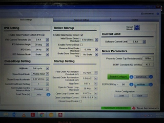
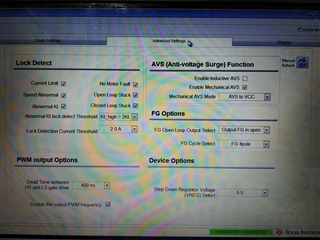
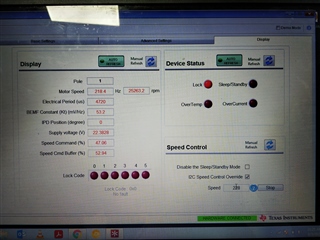
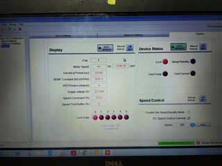
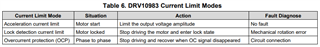
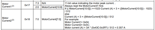
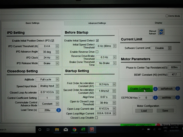
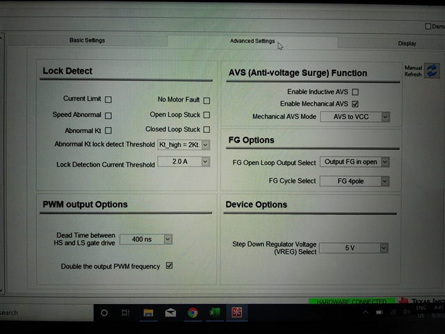
We are using a DRV10983 IC for driving a Maxxon ECX SQUARE 16 L  sensorless brushless BLDC motor, but when we try to run it with all the motor-lock safety checks enabled and a stall condition is introduced, the motor switches off as expected but once the stall torque is removed and the motor switches back on, the motor - driver keeps detecting lock condition and switches off intermittently. Is this normal? how can we avoid this?

  • Hey Jain,

    Can you check register 0x1E and 0x10 and tell me what bits are set here? 

    If you could also provide your EEPROM settings that would be nice. Alternatively you could post some screenshots from the basics, advanced, and display tabs on the GUI.

    After the stall is introduced, and tLOCK_OFF elapses, the device still thinks there's a fault. So checking these registers after tLOCK_OFF elapses will tell us more about exactly which LOCKx is getting triggered. 

    Thanks,

    Michael

  • Dear Michael,

    We have got the screenshots you requested. Attached the same along previous reply.

    Please refer and tell if any more data is required 

    Thanks,

    Jain James

  • Hi Jain,

    Just to clarify, after the stall is removed, and after tLOCK_OFF elapses, the motor still does not spin.

    If that's correct, please see below. 

    I believe that the GUI is not refreshing the left hand side of the screen, thus not showing us which LOCKx got triggered. The problem with having both auto refreshes enabled is that only one will get refreshed at a time, the other you will have to manually refresh. Please manually on the the display tab (left side), and let us know what LOCKx is getting triggered.

    Thanks,

    Michael

  • Hi Michael,

    Clarifying on your question whether the motor spins after stall is removed, it does, but after sometime it stops again even without the stall being present. 

    As to the auto refresh problem, thank you for pointing out this. We will manually refresh the left side from now on and get back to you with further data.

    Thank You,

    Jain

  • Lock bits during intermittency

    Hi Michael,

    I am attaching the image of the lock bits that turned on during the intermittent stoppage of the motor. Please do refer and reply with you inferences.

    Thanks

    Jain

  • Hey Jain,

    I see, you're hitting the overcurrent limit of 2.4A that you have set in the basics tab.

    You may have to adjust this value. Before you do this, I would suggest tuning your lead angle. We have a video on how to do this here.

    Also, we have a tuning guide for DRV10983. Take a look at these two references and let me know your results. If you need additional help on this, please let me know.

    Thanks,

    Michael

  • Hi Michael,

    The over current limit that the GUI shows as being drawn have been tested from our side and the motor seems to have only drawn 0.7 A at that point. We have verified it from our side using a current sensor output on CRO. Infact in none of our stall torque tests did the motor take more than 1.2 A. What would be the reason for it, when the drivers continuous current capability itself is 2A?

    About the lead angle, we look into it using the provided video and tuning guide that you have provided.

    Thank You,

    Jain

  • Hi Jain,

    Can you share the phase current plot? There could be a sharp spike in the phase current that is triggering the OCP fault.

    Please let me know about the lead angle, I think tuning this will likely solve your issue.

    Thanks,

    Michael

  • Hey Michael,

    Could you please guide me through as to how to take the phase current plot, we only had a current sensor that detected the total current going in and also as I told you earlier the total current going in had never exceeded 0.9 A (even under stall condition). 

    According to what I understand, the lead time parameter specifies the lead angle, is that right? If so, I have varied it to see any difference in current draw and there was no visible difference. 

    On Friday, I took out the software current limit parameter that was kept at 2.8 A and changed it to disabled and all the motor lock safeties were already disabled and the motor for the first time drew up to 1.71A.

    Thanks,

    Jain

  • Hey Jain,

    You would take a current probe, with the arrow of the current probe pointing towards the motor (current flowing into the motor). 

    Please tune your kt such the estimated kt matches your programmed kt. I calculated that your programmed kt should be 39.84056.

    The torque constant of your motor is 6.34 mNm/A, with one pole pair. Which converts to 39.84056 mV/Hz. You can see this calculation here:

    Regards,

    Michael

  • Dear Michael,

    The torque constant of our motor is not 6.34 mNm/A, rather it is 8.32 mNm/A (It is the 18V motor given in the motor datasheet). Calculating by the formula you gave, we get 52.276 mV/Hz. We are using a slightly lower value of 47.7 mV/Hz on account of better performance observed under the same.
    In reference to my earlier question on as to why the motor never draws current more than 1 A when software current limit is set at 2.8 A, could you please explain as to why this is happening?

    Thanks,

    Jain

  • Hi Jain,

    I will get back to you shortly!

    Regards,

    Vishnu

  • Hi Jain,

    Are you still seeing "Current limit" fault getting triggered? At what electrical speed does the device trigger "Current limit" fault? Can you review the App note on tuning lead time? Current limit can get triggered when the estimated Kt in closed loop is incorrect. You can tune the Lead time to achieve accurate Kt estimation in closed loop.

    About your question on software current limit, software current limit limits the voltage applied to the motor to ensure the phase current does not exceed the programmed software current limit threshold (refer to section 8.4.6.1 in the datasheet for more details). Your motor does not draw more than 1A when Software current limit is set to 2.8A because the phase current is not aligned with the BEMF voltage. Tuning the lead time will ensure phase current is aligned with BEMF voltage. Equation 7 in section 8.4.6.1 holds good only when  phase current is aligned with BEMF voltage.  

    Regards,

    Vishnu.   

  • Dear Vishnu,

    Yes, we are seeing the current limit fault getting triggered when the motor lock safeties are on. We have tried changing the Lead time from 100 to 400 μs but did not observe any current drop. However, we will ensure the results once more using the method described in the app note.

    We would also like to know, other than the motor lock safeties, software current limit and AVS protection, is there any other in-built safeties that is not accessible from our end, which may cause the driver to switch off and restart the motor?

    We would also like to know what are the ways in which we can get the phase current data other than using probes? 

    Thanks and Regards,

    Jain 

  • Hi Jain,

    Section 8.4.7 in the datasheet lists all the lock functions and protections in the device. In your application, is the device triggering current limit fault only? If that is true, then I don't think there could be any other lock functions that could trigger a fault condition. You can connect a resistor in series to the phase wires and measure the voltage drop but it won't be accurate. Using a current probe would give you instantaneous values and can help through the debug process.

    Regards,

    Vishnu, 

  • Dear Vishnu,

    We have currently disabled software current limit and all motor lock safeties, leaving only mechanical AVS enabled. So according to what you said so far, there won't be any other safety feature that can cause driver to switch off the motor and again start it after sometime. Is that right? If so, please do confirm it

    We have tried tuning lead time using the method mentioned in the app note, however the presence of noise from the sensor output of the current sensor prevented us from observing the variation of current with change in lead time. Although we observed that when lead time was between (400 - 480)μs there was a drop of 0.02 A in the current drawn from the power supply. Should we set our lead time a value between (400-480)μs based on this observation?

    Thanks and Regards,

    Jain 

  • Hi Jain,

    Vishnu will respond shortly!

    Thanks,

    Matt

  • Jain,

    Even if all the locks are disabled, device can still trigger overcurrent protection (OCP) fault . OCP fault cannot be disabled. You can set the lead time to 400-480 us and see if you can operate your motor at higher speeds.

    Regards,

    Vishnu

  • Dear Vishnu,

    As we have said earlier currently software current limit and all motor lock safeties are disabled, leaving only mechanical AVS enabled. So according to what you had said in the previous reply, device can still trigger overcurrent protection (OCP) fault. Then, could you please brief me on how the overcurrent is detected by the motor driver in this case?

    Also, we have tried putting lead times between (400 - 480)μs with software current limit enabled at 3 A  but still the motor driver drew only up till 1 A maximum (as shown on power supply) under stall condition. The estimated Kt is put at 47.7 but the estimated Kt varied between 33 to 56 as the speed varied from 15% to 75%. Can this affect the driver calculations in any way? Could you please confirm if this is normal?

    Thanks and Regards,

    Jain 

  • Jain,

    DRV10983 provides three current limit modes as shown in below table. Acceleration current limit is same as software current limit. DRV10983 has an internal comparator that compares the current, as measured from the FETs with the IOC-limit threshold. Overcurrent (OCP) gets triggered when the FET current exceeds the threshold. 

    I think there is a transient spike in the phase current that triggers OCP. 1A that you are measuring might be the steady state current. You can try DRV10987 which has higher current rating.  

    Regards,

    Vishnu

  • Dear Vishnu,

    We needed your assistance on one more point that we raised earlier, the estimated Kt is put at 47.7 but the estimated Kt varied between 33 to 56 as the speed varied from 15% to 75% (I2C values: - 76 - 380). Can this affect the driver calculations in any way? Could you please confirm if this is normal?

    Thanks and Regards,

    Jain 

  • Hi Jain, 

    Monday the 6th is a U.S holiday and we are out of the office, a team member will get back to you in a couple days.

    Regards,

    Michael

  • Hi Jain,

    Thanks for your patience. Estimated Kt changes due to the change in speed/torque. Lead time should be adjusted to maintain a constant Kt at different load points. When speed changes, the angle between phase current and BEMF voltage changes. This change in angle will cause variation in the estimated Kt. For more details, please refer to this video

    Regards,

    Vishnu

  • Dear Vishnu,

    We have seen this video earlier for tuning the lead time. As we have mentioned earlier lead time has been put at the value where the steady state current drawn is the least for a given speed. Still, the estimated Kt is seen to be varying with load, is this expected?

    Thanks and Regards,

    Jain

  • Jain,

    Yes, the estimated Kt will vary with load. As mentioned in my previous post, when speed changes, the angle between phase current and BEMF voltage changes. This change in angle will cause variation in the estimated Kt. Estimated Kt will be equal to the actual/programmed Kt when the phase current and BEMF voltage are aligned. When both signals are misaligned, a component of phase current will either weaken or strengthen (depending on the polarity of the current) the rotor flux and cause variation in estimated Kt. 

    Regards,

    Vishnu 

  • Hi Vishnu,

    On reading the datasheet further. There are two more protection of which I have queries.
    1. ULVO

    2. Thermal Shutdown

    Can you please share details regarding these too. Details like can it be disabled by user?, what can usually trigger these?, can this contribute to our issue of intermittent stoppages?

    Thank You

    Jain

  • Hi Jain,

    Both faults cannot be disabled. UVLO gets triggered if the supply voltage is below 7.1V (typ). Thermal shutdown gets triggered when the device junction temperature is above 150 deg. The OverTemp status bit (address 0x10 bit 7) is set during thermal shutdown. 

    Regards,

    Vishnu

  • Hi Vishnu,

    We haven't been yet able to resolve the issue of intermittency. We have used your methods of lead time tuning and Kt calculation and still we observe intermittency on some of the motors.

    We also gather from the driver datasheet that if a software current limit is put, it doesn't trigger any error condition but rather only limits the input voltage so that the the driver doesn't draw a higher current than set value. We had tried putting this limit at 2.8 A and 3.0 A and removing all other safeties, but still the intermittency is shown on some of the motors. Also please note all of these motors use the same parameter values apart from the software current limit setting.

    In your replies you have mentioned there is current calculation from the FETs, could you please tell us the conditions under which this current calculation might go wrong, like the actual current could be very less but the calculation might be very high so that it triggers an Over-current Protection.

    Thanks and Regards,

    Jain

  • Hi Jain,

    Vishnu will get back to you early next week!

    Thanks,

    Matt

  • Jain,

    Can you provide more details on what you mean by "intermittency"? Does the device trigger "Current limit" or OCP? Device triggers "Current limit" when the motor current exceeds the programmed current limit threshold in register address 0x28 bit<3:1>. Device triggers OCP when the motor current exceeds IOC_limit (4A typical). Software current limit may be inaccurate when the BEMF voltage is not aligned with phase current. In your case, I believe the device triggers a fault so I don't think this is a software current limit issue. We need to know if the device triggers "Current limit" or OCP. If the device triggers "current limit" the motor might be overloaded. When the motor is overloaded, motor current exceeds the programmed current limit threshold in register address 0x28 bit<3:1> and triggers "Current limit". Device triggers OCP when there is a short circuit condition. 

    Regards,

    Vishnu

  • Dear Vishnu,

    During operation sometimes motor RPM goes to zero and then gets back up immediately which is what we call as intermittency issue. We understand only the driver can trigger such an event. We have disabled all other safeties except the safeties hardwired (OCP, UVLO, Thermal) into the driver. Still sometimes the motor stops and starts once or twice in the whole duration of the operation.

    When all programmable safeties were removed the combination operates without issues till certain loads. However, at higher loads, still the driver - motor combination exhibits intermittent stoppages.

    We just wanted to confirm if there is any chance for the current measured from the FETs might go wrong due to some wrong parameters and trigger OC protection when current is actually below the threshold?

    Regards,

    Jain

  • Jain,

    Current is measured internally through current sense techniques and we expect the sensed currents to be accurate. Since you disabled all the faults, we don't know if it is really the current limit that is getting triggered.

    Regards,

    Vishnu 

  • Hi Vishnu,

    Thank You for that clarification. As we have discussed already we are observing the motor RPM going to zero and then coming back up, which seems characteristic of one of the hardwired fault detection getting triggered and driver placing the motor in high impedance state. Again I reiterate this is after disabling all user controllable safeties. So we would like to know the following points

    1. Whether fault triggering is the only way intermittent stoppages and starts can occur ?
    2. If there are any other ways we might see the same issue please do share your insights on that too ?
    3. Timings details of various hardwired (OCP, UVLO, Thermal shutdown) faults (the time the fault condition should exist, for fault flags to be set and appropriate action taken)
    4. Once a fault state is set and action taken, what is the restart algorithm?
    5. What is the usual debug process for such issues?
    6. Whenever any fault is triggered, what is the status of the 5V output from the IC? Is it affected in someway?

    Regards,

    Jain

  • Jain,

    Disabling all faults doesn't mean that the device would spin the motor flawlessly. We have all these lock conditions implemented to protect the device and motor from unforeseen circumstances such as inrush current, short circuit, motor lock etc. Despite disabling all faults, device can still stop spinning the motor when the BEMF zero crossings estimation is inaccurate. Device might lose sync with the motor due to overload etc., which might affect the zero crossing estimation. Best way to deal with these kind of issues is to enable all faults and debug based on the type of fault getting triggered. Can you enable all faults and check what faults are getting triggered? TI can provide troubleshooting steps based on the fault condition.

    Regards,

    Vishnu. 

  • Dear Vishnu,

    When we enable all faults it usually triggers current limit set at 2.8 A at around 15000 RPM.

    We have a setup to read the register values and we are reading registers 0x10, 0x17 and 0x18, 0x1A, 0x1E, to see what faults are getting triggered and what are the voltage and current values correspondingly. However, while reading the motor current registers (0x17 and 0x18) the readings show values up-to 5.98A. In the motor datasheet calculation it seems till the value of 1023 in the registers the current values is 5.98 A and after that the value starts again from 0 for values up-to 2046. Why are there two positive ranges for current readings? Is one of them indicating the negative direction? Have we understood this correctly or if not please guide us on how to program to read the motor peak current correctly

    Also is there any condition under which the programmed parameters in the motor driver may change during operation?

    Thanks

    Jain

  • Jain,

    Motor current registers (0x17 and 0x18) are not very accurate. I would recommend you to measure the phase current using a current clamp meter and oscilloscope. The programmed parameters do not change during operation.

    Regards,

    Vishnu

  • Vishnu,

    When any of the faults are triggered and driver places the motor in high impedance state, does it also cuts the 5V power to the external circuitry during the time the error condition is present.

    Thanks,

    Jain

  • Jain,

    5V supply from Vreg will be ON when there is a fault triggered by the device. 5V supply will be turned OFF only when device enters sleep mode. 

    Regards,

    Vishnu.

  • Jain,

    Do you need any additional help? If not then we can close this thread.

    Regards,

    Vishnu

  • Vishnu,

    Yes, we wanted that guidance on why the current registers have two sets of positive ranges?

    Regards

    Jain

  • Jain, 

    Did you use the below equations to convert the read back code from registers to the actual phase currents?

    Regards,

    Vishnu

  • Vishnu,

    Yes, these are the equations used to read back code from registers to the actual phase currents

    Regards,

    Jain

  • Vishnu,

    Yes, these are the equations used to read back code from registers to the actual phase currents

    Regards,

    Jain

  • Jain,

    I didn't quite understand the below statement. 

    However, while reading the motor current registers (0x17 and 0x18) the readings show values up-to 5.98A. In the motor datasheet calculation it seems till the value of 1023 in the registers the current values is 5.98 A and after that the value starts again from 0 for values up-to 2046.

    Can you provide the motor current register codes and the corresponding actual/measured current values?

    Regards,

    Vishnu.

  • Vishnu,

    From the driver datasheet, till the binary data equivalent of decimal value of 1022, the equivalent phase current will read a maximum of 5.98 A (Eg:- 3*1022/512 = 5.98 A). After 1022, if we go according to driver datasheet, the equivalent phase current calculation will again start from zero (Eg:- if the motor registers give a equivalent decimal value of 1023, according to datasheet the calculation will be 3*((1023-1023)/512)) = 0 A) and this range will then go on to another 5.98 A reading at 2046. Why is this so?

    Thank You,

    Jain

  • Hi Jain,

    Vishnu will get you a reply tomorrow!

    Thanks,
    Aaron

  • Jain,

    The motor current register outputs positive peak current only. Scaling is done based on the current sensed via ADC. Please pick the appropriate equation based on the motor current register code.

    Regards,

    Vishnu.

  • Vishnu,

    Sorry for the delayed reply. As we have told earlier the equation has been given for decimal counts up to 1023 and another for all values above it.

    Also, while we have found a solution to the intermittency issue we had been dealing with for some time (the cause was noise at the micro-controller input that supplied the input to the driver, which we developed software fix), we have observed a crawling issue with the driver-motor pair.

    Crawling

    We use the I2C channel for command and the command is given in the range of 0 - 380 from the micro-controller. Now, while increasing the speed in multiples of 10 and when the speed command is at 10 (from speed command register) the driver detects a Kt and Speed abnormal fault and then changes into Kt abnormal fault holds the value in the fault register and the speed at this point goes to 20000 RPM (from speed register of driver) and then reduces and settles at 500 RPM. After this for any command increase no change in speed is observed. Now, if the given a command above 70 directly from zero this issue is not there. Please give your insight as to how this might be happening. PFA the parameter settings image with the exception that software current limit is set at 3.0A.Parameters Pg 1Parameters Pg 2

    Thanks,

    Jain

  • Vishnu,

    Just to add to the reply, parameters like input command, speed command, fault code, status register, instantaneous voltage and current and motor speed are being read through a micro-controller and all our info is from that and the visible observations while in driver-motor pair is in operation

    Thanks,

    Jain