This thread has been locked.

If you have a related question, please click the "Ask a related question" button in the top right corner. The newly created question will be automatically linked to this question.

BOOST-DRV8711: Stepper motor drive DRV8711 accidental protection

Part Number: BOOST-DRV8711
Other Parts Discussed in Thread: DRV8711

Dear Expert

Before and after batch proofing accumulated 120~140 PCS, accumulated various failures of 10~20PCS;

Among them, after initialization, the maintaining current is very high, 2~3PCS appear, usually about 10S, the motor can be damaged, oscilloscope grasp the current waveform, prompting the measured value is out of range, oscilloscope enters the protection mode,

If you continue to let the motor carry, the driving sampling resistance will be burned;

Condition 1. If the power-on is normal and the torque is maintained, the motor only needs to run for a while and immediately enters protection, and fault code 0Xe4 (Channel B failure) is reported.Power on the system again to recover the available state. After running, the fault occurs from time to time.

Condition 2. If no fault is reported after the driver chip is initialized, the fault code 0x22 (Channel B &A failure) is reported as long as the STEP is run.Power on again;

Condition 3,.inexplicably and irregularly there is no torque (the sensation triggers the protection mechanism), power on again and restore to normal;

Part of the board, the drive circuit of the periphery is almost replaced, the fault code still exists.

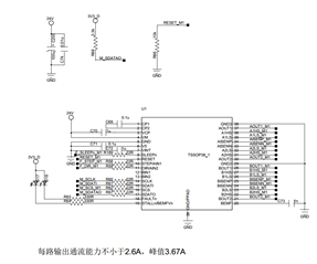
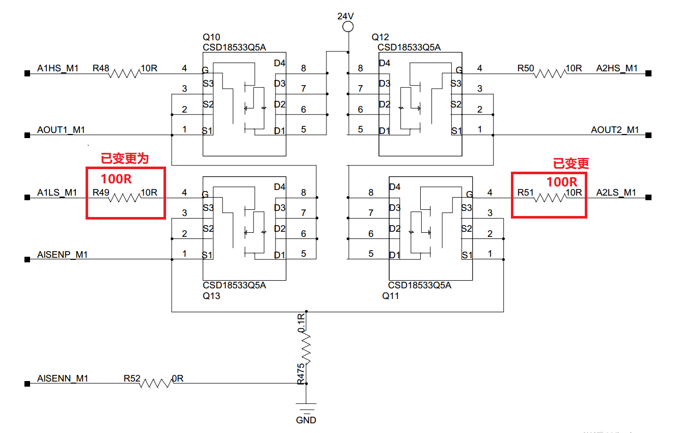
Below is shcemetic :

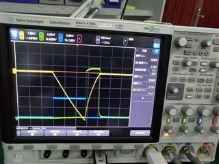
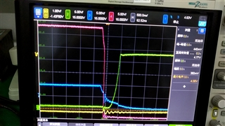
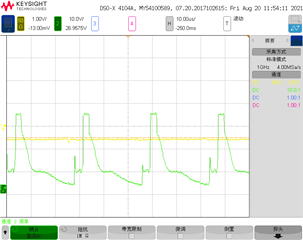
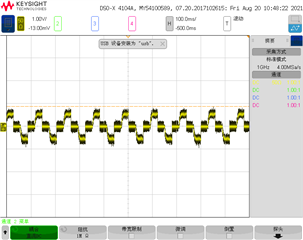
Below is channel B tested high side and lowside gate waveform:

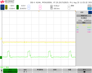
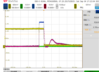
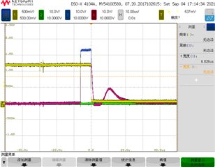
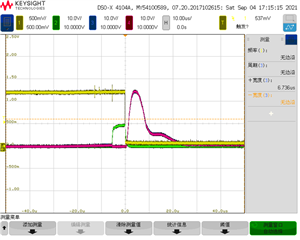
this is the channel B is current waveform:

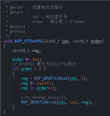
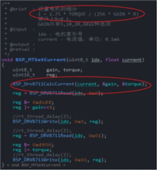
Register we just set ENBL ,MODE ,ISGAN ,TORQUE,

  • Hi Gabriel,

    Can you share all register settings? How do you measure output current, is it current probe?

    Regards,

    Grzegorz

  • Dear Grzgorz

    1.Initialize

    2.Steps set

    3.Current set

    4. Reverse direction pin logic:

    5.The following is an example of a motor :(in short, it is configured to subdivide, current, and direction, and then send pulses to control the motor, nothing else is configured)

    Parameters from left to right correspond to bottom from top to bottom;The registers that are not present here, we don't actually have the configuration, which is determined by the chip default;

  • Gabriel,

    As I understand you only change ENBL, MODE, TORQUE and RDIR registers, the rest of registers have default values.

    Can you try to set IDRIVEP and IDRIVEN registers to lower values and check if it helps? Default values might be to high for your Mosfets and pcb design.

    Regards,

    Grzegorz

  • Dear Grzegorz

    We set IDVRIVEN and IDRIVEP register to 0x00 ,still not to improve the phenomenon .

    Blue and green are half bridge upper and lower pipe control signals.Why is there basically no dead zone, we are all default, no special configuration

  • Hi Gabriel,

    What is timebase on the last picture, is it 600us?

    Dead time should be around 850ns and with long oscilloscope timebase it will not be visible.

    Could you take waveforms in area where LS(low side) gate signal falls down and HS (high side) gate rises with timebase 500ns per division, additionally where LS gate rises and HS gate falls down?

    Could you also add waveforms of output voltage and output current?

    During measurements, please use ground spring hooks (especially for output voltage), bandwidth filter should be turned off.

    Regards,

    Grzegorz

  • Dear Grzegorz

    Yellow current,red high side drive edge, green high side edge, blue low side edge .

    Blue and green are the same half bridge, red is the same full bridge, another control signal is missing (no change)

  • Hi Gabriel,

    Thanks for posting waveforms.

    What is value of current in Amperes (yellow trace)?

    Green trace - output voltage rising time is around 230ns what is very moderate, if LS gate resistor is 100 Ohm I would try something like 68 Ohm instead to decrease switching losses a bit. After resistor change I would check if there is no any ringing on green trace.

    Red trace - I guess it is opposite half-bridge, so we can not see dead time between LS and HS.  HS gate signal is referenced to switching node, it's falling time (the steeper part) is well below 100ns and it might be to fast, we can see some ringing at the the end of slope. It would be interesting to see the very bottom of the red trace and negative value of that ringing. I would decrease IDRIVEN value to slow down HS Mosfet and to limit that ringing.

    Could you try to decrease IDRIVEN value and observe red trace? Its slope should become less steep.

    What is voltage level of red trace at the bottom (second half from the left)? It looks like red trace is at around -4V.

    "another control signal is missing (no change)" - what signal does not change?

    Do the waveforms come from board that works OK or from board that experiences problems?

    P.S. I changed IDRIVEP to IDRIVEN.

    Regards,

    Grzegorz

  • Gabriel,

    For DECMOD I prefer to use "Auto mixed decay at all times - 101" , I think it is the easiest decay mode for DRV8711.

    Regards,

    Grzegorz

  • Hi Gabriel,

    I'm in agreement with Grzegorz regarding lowering the IDRIVE current to minimize the the ringing in the voltage and current waveforms.

    I have a few more questions:

    1. Has this issue been observed in more than one IC and PCB? If not, it would be good to do an A-B-A swap test. Basically remove the faulty IC from the PCB and solder a new IC. Then try to drive the motor. If the issue is still showing, take the faulty IC and solder it onto a new PCB. The point of this test is to get an idea if the issue follows the IC or the hardware.
    2. To confirm, the main issue you are having is the device going into overcurrent protection after driving the motor for some time?
      If no fault is reported after the driver chip is initialized, the fault code 0x22 (Channel B &A failure) is reported as long as the STEP is run.Power on again;
      Can you please clarify what you mean in this statement.
    3. Can you provide another oscilloscope capture showing nFAULT, the high-side FET gate and low-side gate voltage, and output voltage of the half-bridge experiencing the fault. set the nFAULT signal as falling edge trigger and zoom in where the nFAULT signal drops low.
  • Dear Pablo

    We have tried lowering the IDRIVE ,and the voltage and current waveforms still ringing  .And we not sure what exactly the reason may cause .

    1.Yes ,1 board we have 10 pcs DRV8711 and just 1pcs have this failure. We change good IC in failure board ,and we testing .when we start up ,it's protect .

    2.The customer is also protected as soon as the power is on.Because abnormal waveform cannot be measured, it is difficult to locate the customer's problem. By reading the customer's fault code 0X22 (Bin: 0010 0010 is the highest), the fault signal is a-phase overcurrent and undervoltage protection.

    3.Supplementary waveforms are as follows:

    A fault phase

    Yellow: nFAULT, Green: A1LS, Blue :A1HS, Red: AOUT1, :

    Zom in : Yellow: nFAULT , Green:A2LS,Blue :A2HS ,  Red:  AOUT2 ,:

    Zom in :Yellow: nFAULT , Green:B1LS,Blue :B1HS ,  Red:  BOUT1 ,:


    Yellow: nFAULT , Green:B2LS,Blue :B2HS ,  Red:  BOUT2 ,:

  • Hi, Gabriel,

    Our office is closed today for the US Labor Day holiday. We will be back at work tomorrow. 

    Best regards,

    Don

  • Gabriel,

    Since we had offline discussion and found the 100 series gate resistor causing the high FET and low FET shoot through which damaged the sense resistor, let me close this post. 

    You can start a new post if you have other questions or contact me to do further debugging work.

    Regards,

    Wang Li