This thread has been locked.

If you have a related question, please click the "Ask a related question" button in the top right corner. The newly created question will be automatically linked to this question.

DRV8825: Break down and stucked in 1\16 mode

Part Number: DRV8825

Yes, it is a very strange case, but the repeatability is enormous.

On a new batch of my device, these drivers began to fail. Approximately 50%. I'm in panic.
(old batch consists about 800 drivers and it's working properly)

What it looks like:

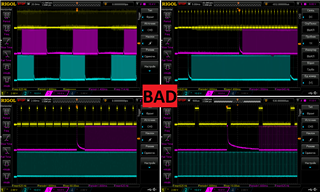
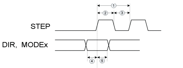
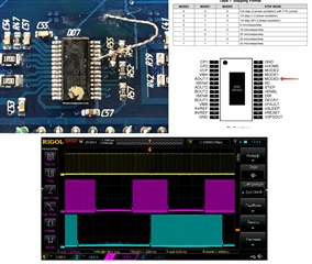
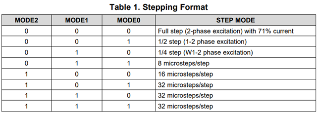
At some point during the work (or at once) the stepper motor began to spin slowly (step freq is constant). I had discovered with oscilloscope,that driver began to work in 1\16 microstep mode.  All MODE-GPIOs directly on the ground, that's provide "no microsteps mode". I'm working without microstepping. So I have replaced this driver to another board and found, that driver stucks in 1\16 microstep mode forever, regardless of MODE0-1-2 (I tried to pull-up MODE_0 for 1\2 microstep mode, but nothing has changed).

It's seems like something is failed inside the driver. If I increase the step frequency by 16 times (like goes to 1\16 mode), the driver works properly.

FAULT pin in good state. Soldering is good, I checked it, MODE pins on the ground. 

I'm in deadlocked situation.

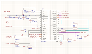
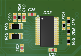
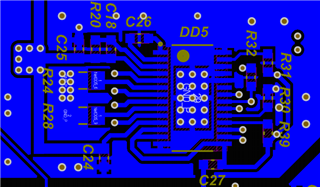
The old batch and the new batch have the same sch, pcb and code. I suppose it works on the brink of failure=)

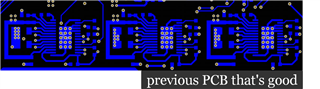
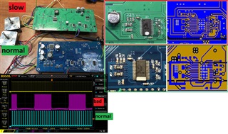
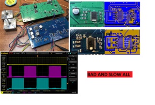
I have not found such cases. SCH, PCB and oscilloscope screenshots of a GOOD and BAD driver are attached.


  • Hi Egor,

    Just one hint before I go on my holidays. I would check why there is so large PWM noise present on STEP input on a bad board.

    It is much higher than on a good one and may cause DRV8825 malfuntion. I would also swap DRV8825 between old good board and a new bad one and see if failure follows an IC.

    Thermal relief between DRV8825 thermal pad and ground plane is a bad thing.

    Regards,

    Grzegorz

  • Egor,

    What is the tWH(STEP) and tWL(STEP) setting? timing 2 is tWH(STEP). According the recent research, when tWH(STEP) is longer than 4.16us, DRV8825 won't miss the STEP pulse.

    BTW, can you make solid copper connection around the thermal pad? So, we can have a good thermal contact.

    Regards,

    Wang Li

  • Yes, PWM noise is presented. But I suppose that it's a feedback, cause I have 3 drivers on board and one STEP source (via multiplexer)(one of them is good).

    And a good point about bad GND POLY. Because the previous PCB version didn't have a Poly at the same layer (attached). I should have to repeat it  or fill thermal pad by region. BUT! The board has 4 layers. One of them is GND. Can it be the reason of failure in this case?

    Anyway the bad driver can not be recovered, It's always stayed in 1\16 mode...

  • tWH = 200 uS; tWL = 1400 uS; 

    About thermal PAD I wrote in previous reply. Can fix it next time only.

    Anyway it's hard to believe that on a 4-layer board (one of them is GND) this bad poly-thermal-Pad is the reason of failure.

  • Hi, Egor,

    Our office is closed today for the US Labor Day holiday. We will be back at work tomorrow. 

    Best regards,

    Don

  • Hi, Egor,

    I saw the bad one had a current spike in front of a group of PWM pulses and had a current tail after a group of PWM pulses. Would you remove R30 to change the decay mode setting from slow decay to mixed decay? If you can measure the output current, it would help us to understand it more.

    "I have 3 drivers on board and one STEP source (via multiplexer)(one of them is good)." If we swap the device on the board, does the issue go with the device or the location?

    Regards,

    Wang Li

  • I removed R30. Nothing changed. 

    Unfortunately, I cannot measure the current.

    BUT! Problem in DRV8825 - the bad one stucked in 1\16 mode. I pulled up MODE_GPIO to change microstepping - nothing is changed. 

    Next experiment: if I increase freq (for the bad one) by 16 times - step motor works normal like with the good one.But this is not a solution.

    DRV8825 breaks down and cannot be repaired. I want to find the reason for this. The only difference between OLD version is bad GND-POLY.

    This is just a theory.

  • Hello,

    We are investigating and will reply within a few days.

    Regards,

    Shinya Morita

  • Shinya,

    Thanks,

    Hello, Egor,

    Mode0, 1 and 2 hardware pins control the micro-stepping setting. This is straightforward. Please check those three pins soldering condition.

    Since we have the good board and the bad board, would you swap the DRV8825 between the good board and bad board? So, we can see if the issue goes with the DRV8825 device or the board?

    Regards,

    Wang Li

  • I've swapped DRV8825.

    STEP signal is CONSTANT (tWH = 200 uS; tWL = 1400 uS;)(Same code)

    There are two identical step motors.

    On oscilloscope:

    yellow ch. - STEP;

    pink  ch.- B- of GREEN;

    blue ch.- B- of BLUE oard.

    Experiment A: GREEN board(NEW PCB), DRV#1 (dot mark)   VS   BLUE board(OLD PCB), DRV#2(line mark). 

    The step motor of GREEN board rotates 16 times slower than еру other. It's like 1\16 mode again.

    THAN I've swapped DRV8825.

    Experiment B: GREEN board(NEW PCB), DRV#2(line mark)   VS   BLUE board(OLD PCB), DRV#1 (dot mark).

    There is the same view at the oscilloscope and the same speed of all step motors. 

    I decided repeat experiment with changing microstepping mode and pulled up MODE0 (1\2 mode)

    Experiment C: BLUE board(OLD PCB), DRV#1 (dot mark). (that I take frome GREEN board).

    MODE0 > 3V3, MODE1 > GND, MODE2 > GND,

    And step motor begin rotates slower...

    It looks like the green board make DRV8825 slower for 16 times forever. Is there some CLK module that's can be broken?

  • Hello, Egor,

    Good finding. If put DRV#2(line mark) back to blue board, the motor speed is slow, we can confirm the "MODEx" pin damage.


    On the schematic and layout, I saw MODE0,1,2 were connected to ground. It is hard to believe MODEx pin damage. Actually, green board thermal performance should be better. I would like to make the thermal pad have a solid copper pour connection which can further improving the thermal performance.

    How many boards do you build? Do all green board have the same issue?

    Regard,

    Wang Li

  • Actually, I'm not sure that it is thermal problem(I mean high temperature during the work). Because (from example) the green board does not work before. It did not work at the first "on". And current limit is only 0.66 Amp. 

    P.S. And what about Experiment C. A made 1\2 mode, and the driver became rotates slowly, like ((1\16) \ 2) = 1\32 mode...

  • Egor,

    Yes, the thermal issue is not related to micro-stepping setting. According to the MODEx pin table, the green board made MODE2=1 and MODE1=0. But, the MODE0 pin still work to give 32 microsteps. 

    I cannot believe that the green board MODEx pin ground connection can damage the device.

    1. Would you try a new device on a new green board? 2. Would you check the green board MODE2 pin connection?

    Regards,

    Wang Li

  • I will check tomorrow about 10 boards for more information. I'm sure that connection of MODEx is Ok, cause those boards mounts on conveyor. I have about 440 boards = 440*3=1320  DRV8825 =)

  • Egor,

    Thank you...we will wait on your response.

    Regards,

    Ryan

  • I've checked 10 boards = 30 drivers.

    12 are bad. Don't work at the first "On". 18 are good. Summary there are about 40% defect.

    There are two data codes: 06TG5 C6C1 and 05TG5 ALV1.

    I'm starting to think about re-routing the PCB and replacing the driver with another, for example DRV8889. 

  • Hello, Egor,

    The only thing I can think about is: an ESD event damage the MODE2 and MODE1 pin. Please contact local sales or our quality engineer to do a failure analysis.

    Regards,
    Wang Li