Other Parts Discussed in Thread: DRV8424
Dear Forum, Dear TI Experts,
we replaced a stepper motor driver due to EOL notice.
On the legacy board, it was used a stepper motor driver from Allegro Micro Systems. A3977SED-T ( Stepper Motor Controller, 2.5A, NMOS, PQCC44 ).
Looking for alternatives with the same functionality we have found: A5977GLPTR-T ( Stepper Motor Controller, 2.8A, PDSO28 ) also from Allegro Micro Systems.
Since we always had good experiences with components from TI, we searched for an equivalent via the cross reference search and found one.
-> DRV8818PWPR
according the DataSheets a 1:1 replacement.
Our application requires a constant speed of the motor of 401.57 rpm, since we are measuring samples in a disk with fixed segments.
So if the speed of the motor varies, we miss the right time slot to measure our samples.
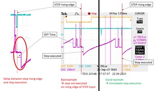
Tests with the new driver shows, that the motor speed is inconsistent, due to a delay in applying the next step.
Driver Settings:
VMx: 25 V
VCC: 5 V
USMx: 0 --> FullStep
SRn: GND --> synchronous rectification enabled
Vref: 3.178 V
Rsense: 0.33 Ω
Itrip: 1.2 A
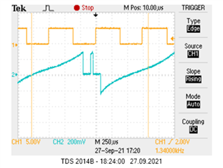
step frequency: 1.34 kHz
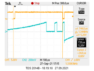
compared a legacy board with a new one shows that the drivers are working different.
We could measure that the driver applies the next step only when the winding current is decreasing and toff time has expired or the winding current is increasing.
lower the toff time increases the chopper frequency, but the "dead time" still exists. (R= 12 kΩ / C = 1 nF --> 12us)
extending the toff time decreases the chopper frequency, "dead time" stands, (R= 100 kΩ / C = 1 nF --> 100 us)
Varying the voltage on the DECAY pin, does not have any effect!?!
According E2E Posts, the DRV8818 can only operate in slow decay mode for full step setting
https://e2e.ti.com/support/motor-drivers-group/motor-drivers/f/motor-drivers-forum/634627/drv8818-mixed-decay?tisearch=e2e-sitesearch&keymatch=DRV8818#
Searching for a solution we have mounted two diodes from the STEP input to RCA and RCB, to force the driver into PWM ON mode so that the next step is created immediately.
This solves the problem, but does not look like the right solution. Are we missing something here?
We are very appreciative of any information you may provide.
Stepper_Schematic_legacy_A3977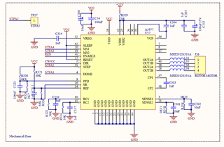
Stepper_Schematic_new_DRV8818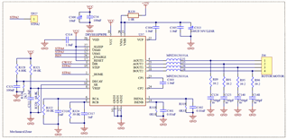
Comparism_Oscilloscope_Pictures
Comparism_Oscilloscope_Pictures.pdf
Stepper_Schematic_new_DRV8818_with_fix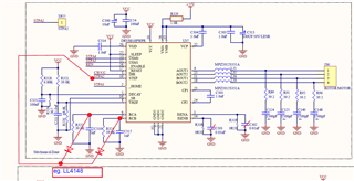
Best Regards,
Fabio