This thread has been locked.

If you have a related question, please click the "Ask a related question" button in the top right corner. The newly created question will be automatically linked to this question.

DRV110: Incorrect hold and peak current setting on DRV110A

Part Number: DRV110

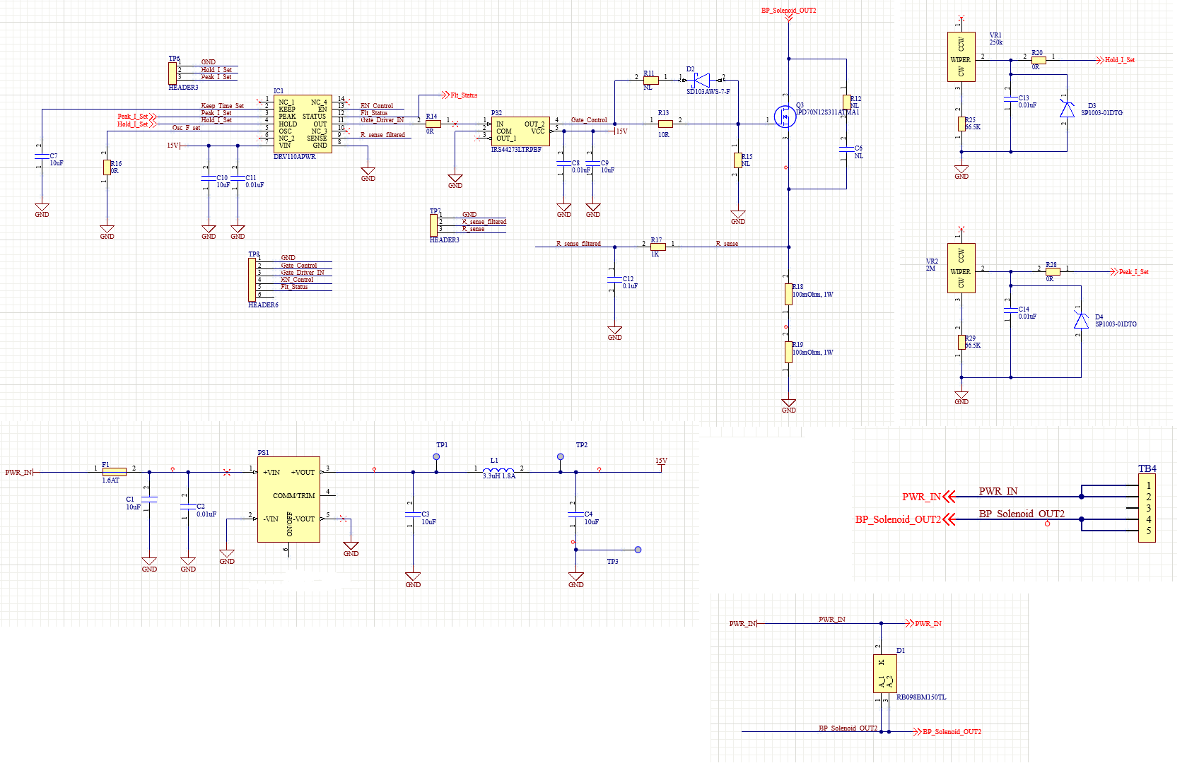
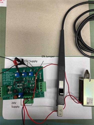
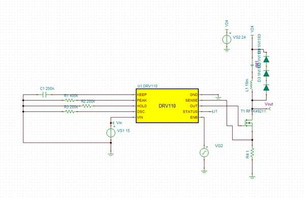
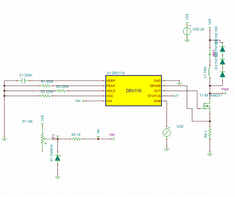
I have designed a custom board on DRV110 to control solenoids of different hold and peak currents, settable by pots on board. The board is supplied with a voltage of 24V which is also the supply voltage for solenoid. The IC is powered by 15V generated from on board DC DC converter. 

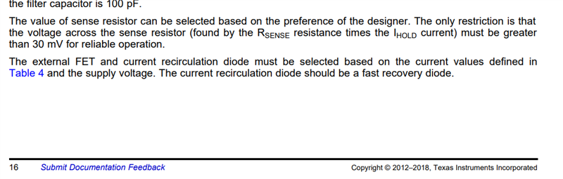
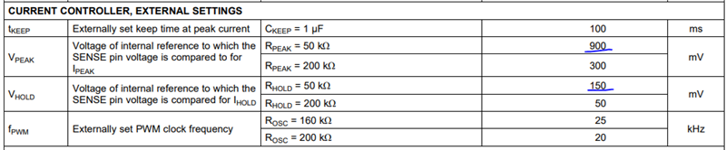
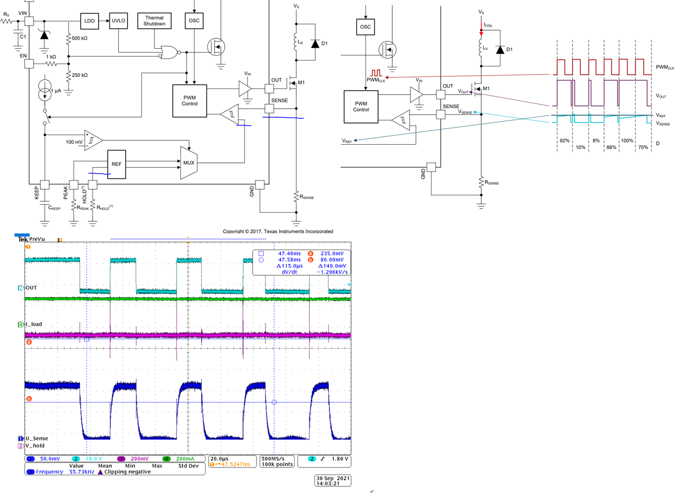
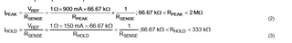
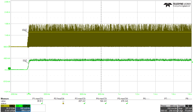
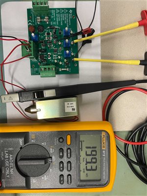
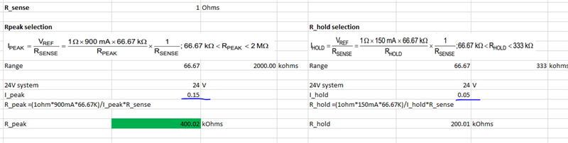
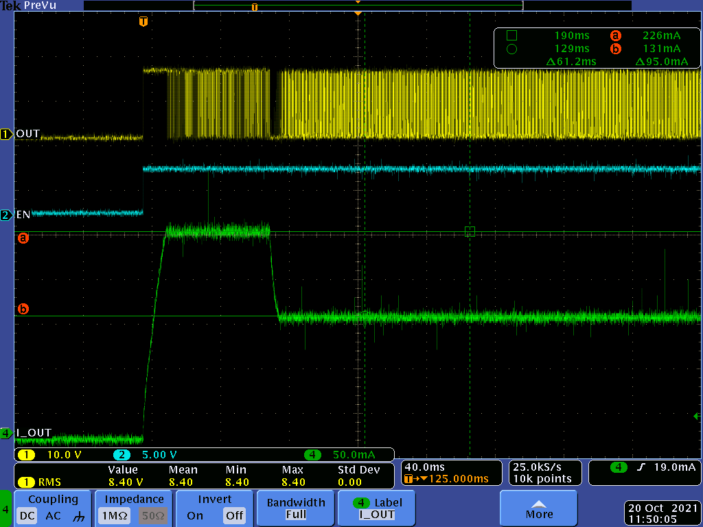
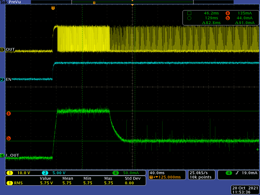
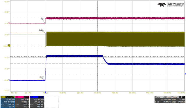
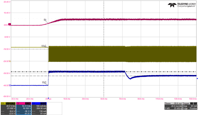
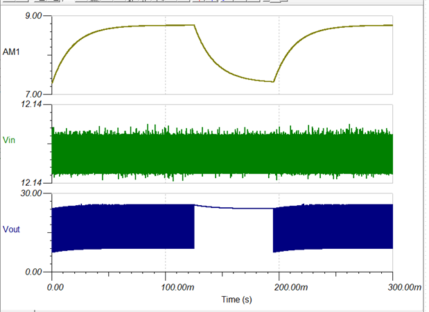
I am trying to set peak current of 0.48A and hold current of .35A. The sense resistor value is 0.2 Ohm. The calculated Rpeak and Rhold are 625kOhms and 142kOhms respectively which is set by the pots. However the current is not as expected, the OUT signal which drives the FET gate is high all the time and current remains constant ( limited by R of solenoid) irrespective of value set by pots.

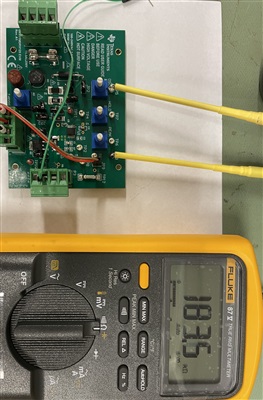
I do not understand what am I missing here. I have checked the resistance on driver pins and they seem to be correct. The voltage on hold and peak pin of driver is 1V which is different from datasheet's value for similar values of hold and peak resistance. The drop across sense resistors is more than 30mV for these set values.

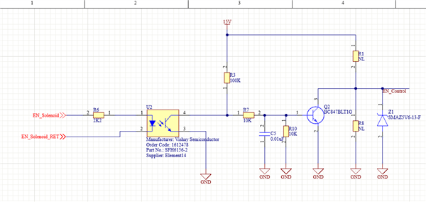
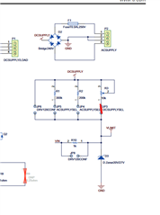
Attached relevant sections of schematics.

  • Hi Nirmala,

    I think the issue here maybe the RSENSE resistor value. You have to select the RSENSE resistor such that the voltage across is less than 30mV. Currently, at 0.48A peak and 0.2Ω Rsense, the voltage across the resistor will be 96mV. I suggest choosing >0.7Ω to ensure the RSENSE voltage is below 30mΩ. You'll have to resize the RHOLD and RPEAK values to get the desired peak and hold current values.

  • The datasheet says otherwise.

  • Can you also clarify if there is a relationship between sense resistor and the voltages on peak and hold pins.

    The datasheet mentions following values:

    I am observing 1V on hold and peak irrespective of the R_peak and R_hold values.

    Also I increased the Rsense from 0.2Ohm to 0.5 Ohm. Now the gate drive signal changed to a PWM instead of 100% ON but the output currents are not what they should be as per hold and peak resistance values. 

  • As per datasheet the OUT signal to gate switch off when v_sense reaches Vref ( which after peak time period is V_hold). 

    In my case it does not even reach 1/4th of the V_hold value and switches off the gate drive (attached image).

    So not only am I getting wrong values on hold and peak voltages the comparator behaviour is also not proper.

  • Hi Nirmala,

    I mistook I_PAEK for I_HOLD. My apologies the datasheet is correct.

    Can you also clarify if there is a relationship between sense resistor and the voltages on peak and hold pins.

    The equation above shows the relationship. VREF is the internal reference voltage (V_peak and V_hold). So for a 625kohm R_peak, V_peak=96mV. If you are measuring 1V for both PEAK and HOLD regardless of the resistance value, then there is definitely something we need to investigate.

    I am observing 1V on hold and peak irrespective of the R_peak and R_hold values

    I'm thinking somehow the HOLD and PEAK pin voltage is being latched to 1V. You are using a potentiometer to set the resistance values. How do you have it set-up? There might be some leakage current on the pull-up resistor causing  a higher voltage drop.

    Can you disconnect the potentiometer or set it to 0Ω and measure the PEAK and HOLD voltages? If RPEAK or RHOLD is decreased below 33.33k (typical value), then the reference is clamped to the internal setting of 300 mV for PEAK and 50 mV for HOLD. If you measure any other values, then there might something else causing the voltage to be higher than expected.

    So not only am I getting wrong values on hold and peak voltages the comparator behaviour is also not proper

    The reason for the improper current regulation is due to the wrong hold and peak reference voltage values. Please do the test I described above to debug this problem.

  • Yes, I am calculating R_peak and hold using these formulas.

    There is no pullup on hold and peak pins, just the potentiometers to Gnd as shown in diagram above(I have removed the ESD diodes). I had tested with setting the pots to 0hms and I got 214mA as hold current instead of 50mA.

    One weird behaviour I observed is that if I keep the enable ON (Floating) and then turn on the power supply the hold and peak currents are exactly as per pot settings. Keeping the power ON if I do a toggle on EN signal the currents go back to wrong values. Looks like a hold and peak are sensitive to leakage on EN pin.

    My enable circuit is below. Have you observed this sort of behaviour before?

    Also keeping the EN On and setting pot to 0 Ohms gives me a current of around 84mA which is closer to 50mA as expected.

    Can you also let me know if the enable circuit is modelled in the spice model as so that I can try and simulate this in TINA.

  • I tested circuit after removing Z1 and Q2 so that EN signal is floating and connected EN_control to Gnd using a test point for disabling and remove gnd connection for enable. But the behaviour is same i.e. if enable is kept floating and power is turned on the currents are proper and if enable is done after power is ON, the currents go to wrong values.

  • Hi Pablo,

    You should be able to repeat this behaviour on the DRV110 development board by supplying an external 15V instead of board derived supply.

    I disconnected all the jumpers except JP1(Fly back diode in circuit) and JP2 (R_osc set to around ~170Kohm). Connected external 15V on TP11 and TP9 (Gnd). 

    In this setup if you keep enable floating and then turn on the 15V and 24Vsupply the hold and peak current will be as set by the pots, but if you keep enable grounded and turn on 24 and 15V supplies and then make the enable floating, the current values will be wrong.

    I am expecting a good root cause from TI this time as it can be reproduced on EVM too. Thank you for your support.

  • Hi Nirmala,

    Can you also let me know if the enable circuit is modelled in the spice model as so that I can try and simulate this in TINA.

    Yes it is. if you go to the DRV110 product page on ti.com, you'll find the TINA model at the bottom of the page.

    Have you observed this sort of behaviour before?

    I have not. This seems to be a very unique issue.

    In this setup if you keep enable floating and then turn on the 15V and 24Vsupply the hold and peak current will be as set by the pots, but if you keep enable grounded and turn on 24 and 15V supplies and then make the enable floating, the current values will be wrong.

    This is interesting. I'm going to go to the lab early next week to test this with an evaluation board. Please allow me 2 business days to look into this a little more in detail.

    Thanks in advance for your patience.

  • Thanks Pablo. I will be waiting on inputs from your end. 

    I did some more tests and have some empirical data which might be useful in your debugging. The current (EN after power ON test) is roughly 180 mA higher than the set value when R_sense is 0.5R and around 80-90mA higher than the set value when R_sense is 1 Ohm. 

  • Hi Nirmala,

    Thank you for the information. I just received the DRV110EVM from our warehouse and will be conducting tests tomorrow in the lab. I will give you an update tomorrow.

  • Hi Nirmala,

    I was not able to replicate this issue on my end. I think it may be due to the load. I used both an inductive and resistive load but was not able to observe the issue you were having. Although I did observed the peak current decrease when increasing the PWM frequency (ROSC). This can be expected for inductive loads since the there is less time for the current in the inductor to rise to the expected PEAK value.

    What is your ROSC value? What is the inductance/resistance of your load?

  • R_osc around 170Kohm on EVM. I have tested with two parts.

    Part 1 : L= 235mH @1kHz and 60mH @100kHz R-150 Ohm (https://au.rs-online.com/web/p/linear-solenoids/0346356/)

    Part 2: L= 79mH @1kHz and 18mH @100kHz R-65 Ohm  (https://au.rs-online.com/web/p/linear-solenoids/0349715/)

    It is quite repeatable on my end on EVM for both the parts. Just to clarify you have supplied the IC's 15V separately like I explained ( disconnect all the jumpers except JP1(Fly back diode in circuit) and JP2 (R_osc set to around ~170Kohm). Connected external 15V on TP11 and TP9 (Gnd))?

  • Hi Nirmala,

    Thank you for providing the load details. I will attempt to recreate it in the lab today or tomorrow. I will provide you an update as soon as I have something.

  • Hi Nirmala,

    I followed your procedure but I'm still not able to replicate the problem. When I turn on the 24 and 15V supplies, the load current is about 470mA and remains at that level indefinitely.

    I get the same current value regardless of whether the EN is floating before power is provided to the board or EN is toggled after power up. And just to confirm. You observe this problem on both your board and EVM?

    In order to help me with debugging, can you list out your exact procedure you performed on the EVM to obtain the results you did. I will closely follow your steps to hopefully get the same results.

  • Hi Pablo,
    Yes, I observe this both on EVM and my board. Also, my board works fine ( provides currents as set by R_hold and R_peak) if the 15V of IC is derived from the 24V using pot in series instead of a DCDC.
    I will send you a video of the whole setup, along with the issue being repeated.
    Just to clarify when say load current is 470mA, is it as expected by your pot setting for R_hold and R_peak? To me the currents you are getting too does not look right unless you are setting same current value for hold and peak. 
    In your setup can you also test lower values of I_hold and I_peak, like 30mA, 50mA, 100mA with the separate supply arrangement and let me know results.
  • Nirmala,

    Thank you for sending more information.  We will wait for that and reproduce.

    Regards,

    Ryan

  • Can the team give me response on my questions in the previous post? Are you able to get current values set by the pots in your setup with separate supply voltages. 

    Can you try setting lower values of I hold and let me know if you are able to get those in your setup like 30mA, 50mA, 100mA. 

    As mentioned previously the graph in Pablo's post looks like abnormal behaviour of driver unless same value of I_peak and I_hold were set.

  • Nirmala,

    Pablo is out on vacation this week.  I will have to get it reassigned.

    Regards,

    Ryan

  • Steps with images to repeat issue:

    1) Remove all jumpers from board except JP1 and JP2.

    2) Connect 24V supply on P1 connector.

    3) Connect 15V supply on TP11 and TP9.

    4) Set Rpeak to 400K Ohm.

    5) Set R_hold to 200k Ohm

    6) With Rsense of 1 Ohm we should get following current values. I peak =150mA, I_hold = 50mA.

    CASE I: The Enable jumper JP9 is installed (Driver enable off).

    7) Turn on 24V supply.  

    8) Turn on 15V supply ( DO NOT turn on both together).

    9) Remove JP9 to turn on driver.

    I got following current values with this sequence.

    These values are not as expected from calculation as shown above.

    CASE II: Remove JP9 jumper (Driver enable ON)

    1) Turn OFF both supplies.

    2) Remove JP9 jumper, driver is enabled before power on.

    3) Turn ON 24V supply.

    4) Turn ON 15V supply.

    5) Solenoid gets activated as soon as 15V is turned on as enable is already ON.

    I get following currents with this sequence:

    These current values are close to what is expected as per calculation.

    With the steps explained above I am sure your team should be able to reproduce the issue. I am desperately waiting on some resolution on this.

  • Hi Nirmala,

    Since Pablo is out of office, let me support this post. I will review your post and feedback to you in a few days.

    By the way, Rosc should be greater than 160Komh (Datasheet page 11). Please change it if you set smaller than 160Kohm on TI-EVM now.

    regards

    Shinya

  • The R_osc is around 180K-185K Ohms in above tests.

  • Hi Nirmala,

    Thank you for your confirmation.

    regards

    Shinya

  • Hi Nirmala,

    Apologies for the late reply. I figure out that the reason for the difference in my results is due the EVM I was using not working. I will be using a new one for testing. Please give a business day to run the tests.

  • Hi Nirmala,

    I ran the tests with a new EVM and got similar results as you for CASE I. However, the results for CASE II are different. I think the difference here is due to the load. What is the inductance and resistance of the load you are using.

    I'm still investigating why this behavior is different from the expected behavior.

    I will reply back with hopefully better news by 11/08.

  • The part used in step by step reproduction of the issue is part 2 given in my previous posts.

    Part 2: L= 79mH @1kHz and 18mH @100kHz R-65 Ohm  (https://au.rs-online.com/web/p/linear-solenoids/0349715/)

  • Hi Nirmala,

    Thank you for providing the info. I will go to the lab to redo the test and use similar resistance and inductance values you are using. I will update you in 24 hours.

  • Hi Pablo,

    Any update on your end? Were you able to get to the root of the issue?

  • Hi Nirmala,

    Unfortunately I don't have much updates from my side. I've been occupied with other tasks last week and didn't get to go to the lab and run the tests.

    I should be able to have something for you within 48 hours. Sorry for the delays. I appreciate your patience.

  • Hi Pablo,

    Any update from your side?.

    Do we at-least have clarity on if this behavior can be corrected with part update or will I have to do a PCB redesign to make it work as expected.

  • Hi Nirmala,

    I didn't get the chance to work on this last week. I was busy with other tasks. I have some time today so I will prioritize this. I will provide you with an update today. 

  • Hi Nirmala,

    I spend this afternoon trying to understand what is happening. I followed your procedure and was able to replicate the results. See waveforms below:

    CASE1: open EN after power up.

    CASE2: EN open before power up

    A weird phenomena I observe is that regardless of which test case was perform, RHOLD increased by around 100kohm. When EN is shorted, RHOLD=200kohm and when EN is open RHOLD=~300kohm. This may explain why the hold current is slightly higher than the expected 50mA. As for CASE1, I was able to recreate it with one EVM but I ended up damaging it and replacing with a new EVM. In the new EVM, with same set-up, I was not able to replicate it again. I got the same IHOLD and IPEAK values as in CASE2.

    My first assumption is that the potentiometers is causing the resistance increase. So remove the potentiometers and added leaded resistors. I still observe the resistance increase when EN is open.  Measuring the current through the resistor and VHOLD, the current goes up to 9.5uA and VHOLD to 9.9V (~100kohm). This confirms the resistance increase when EN is open.

    Another thing I should point out with your set-up is that you connected the 15V supply on TP11 which bypasses the 1kohm resistor between V_LIMIT and VIN. The datasheet recommends a resistor of 500ohm in series with VIN when VIN<15V for optimal operation. I connected the 15V supply on TP10 (VLIMIT) instead but the results were the same.

    TO conclude this thread, I'm still not 100% sure what the reason for the inaccurate hold and peak currents. I have exhausted my debugging capacity and I don't think doing bench testing at this point will get us any closer to the root cause. My team recently inherited the DRV110 from another group within TI so our design team is not familiar with this device. So analyzing the internal circuit of this driver may not be possible. As a last attempt to understand this behavior, I recommend running a simulation in TINA (can find example schematic model in ti.com/product/drv110) Make sure to use the exact passive values and supply values.

  • Thank you Pablo for your response.

    I tried simulation using the schematics provided on DRV product page. I modified R_hold and peak as per my design and added another supply for driving solenoid, with Gnd common to IC's Supply as shown below. Updated solenoid parameters as per my part(10mH,65R).

    I did two simulations -  one with VS2 as 15V and other with VS2 as 24V. In both cases the solenoid supply is still a separate supply with Gnd common to VS1.

    I got correct current values when supply value was kept same as IC's supply and really weird currents (order of 6-7Amps) when supply voltage was 24V.

    Case 1 : Solenoid supply voltage equal to IC supply voltage (VS1= 15V; VS2=15V)

    Red channel is solenoid current and green is IC V_out.

    Case 2: Solenoid supply voltage at different value than IC supply voltage (VS1=15V; VS2 =24V)

    The current in this graph is at around 7A even when driver is off and reaches peak of 8.76A. Looks like IC is not regulating here as the current does not seem to change from peak to hold value.

    Note this current value is different from what we actually observe on EVM when we supply 24V to solenoid and 15V to IC. I do not know if the sim model was tested with this sort of schematics or if the model is a true representation of the silicon.

  • Hi Nirmala,

    The current in this graph is at around 7A even when driver is off and reaches peak of 8.76A. Looks like IC is not regulating here as the current does not seem to change from peak to hold value.

    One thing I noticed on your schematic is that you did not place any series resistance in Vin. The datasheet recommends to add a resistor to limit the current when Vin>=15V. If not, this may cause the device to not work properly. I can also run simulations in parallel with you. To save me some time, can you send me your TINA project.

    Note this current value is different from what we actually observe on EVM when we supply 24V to solenoid and 15V to IC. I do not know if the sim model was tested with this sort of schematics or if the model is a true representation of the silicon

    True. The simulation model won't be a true representation of the real IC but we can at least use it to debug. From the simulations, we know that there is abnormal behavior when Vin=15V and Vs=24V. Our bench testing and simulations prove this (although results are not exactly the same).

    Another simulation we can do is using Vin<15 and Vin>15 but not equal to 24V.

  • Hi Pablo,

    I tried simulations at 14V Vin and 20V V_in with series R of 1k but the results are same as before. Please attached the schematics I am using for my simulations.

    sbwm004a (1).tsc

  • Hi Nirmala,

    Thank you for the simulation files.

    Please give me one day to run my own simulations

  • Hi Pablo,

    I did one more simulation by changing the supply arrangement of IC as in EVM (derived from solenoid supply using resistors and zener).

    In this circuit too I get wrong current values. Attached sch and result from the same.

    Observe current is in range of Amperes instead of mAmps. Attached schematics file for your use.

    6761.sbwm004a (1).tsc

  • Hi Nirmala,

    Apologies for late reply. I think the reason for the very high current in the simulation is due to having no resistance in the inductor. I suggest choosing an inductance and resistive value similar to your solenoid.

  • Nirmala,

    I think I know what could be happening here. Step 5 of the power up procedure of the user's guide mentions to add a series resistance at Vin when Vin is equal to 14V. This will limit the current at Vin and prevent any damage to the IC. The EVM comes with a 10kohm potentiometer which can be enabled by shorting JP3 and leaving JP8 open. First set R3 to 10kohm and observe is this helps with the current regulation.