


Other Parts Discussed in Thread: MSP430F5529, DRV8343-Q1, MSP-EXP430FR5969, MSP-EXP430FR5739, MSP430FR5969, MSP430FR5739
The DRV8343S-Q1EVM and DRV8343H-Q1EVM both include an onboard MSP430F5529 MCU that is used to evaluate the DRV8343-Q1 device by providing sensored or sensorless trapezoidal motor control and connectivity to a offline GUI application. When purchasing the EVM, the MCU comes automatically flashed for sensorless trapezoidal control.
The EVM tool page also includes a downloadable Firmware Package, which includes sensorless trapezoidal, sensored trapezoidal, and independent mode firmware projects for Code Composer Studio
- If IT blocks the installer for the software package, you can download the following zip folders for each firmware solution below. Extract the firmware files into a local directory then import the CCS Projects into Code Composer Studio.
- Sensorless Trapezoidal: DRV8343_MSP430F5529_Trapezoidal_Sensorless_BLDC.zip
- Sensored Trapezoidal: DRV8343_MSP430F5529_Trapezoidal_Sensored_BLDC.zip
- Independent Mode: DRV8343_MSP430F5529_Independent_Drive.zip
- 1x PWM mode firmware is available here: 3857.DRV8343_MSP430F5529_Trapezoidal_Sensored_BLDC_1xPWM.zip
- DRV8343-Q1 EVM GUI (DRV8343Q1-1.0.0_EVM) that automatically identifies the firmware project flashed onto the MSP430 MCU
In order to flash firmware onto the MSP430F5529 on the EVM, an MSP-EXP430FR5969 or MSP-EXP430FR5739 LaunchPad is required. Follow the procedure below. [NOTE: There is no debugger on the DRV8343x-Q1EVM. Trying to flash the program by connecting the USB to the EVM will result in the message "Error initializing emulator: No USB FET was found".]
1) Obtain an MSP-EXP430FR5969 (available on samples.ti.com) or MSP-EXP430FR5739 (available on the TI Store). These MSP430 LaunchPads include the SPI-by-wire 6-pin, 50-mil wide connector on the right side of the board. You may need to solder 4-pins (SBWTDIO, SBWTCK, 3V3, GND) using a 50-mil 4-pin header to the LP as shown below in the red circles. Pins 1 and 6 of the connector are not used, and pins 2-5 correspond to the four SPI-by-wire pins needed for flashing the MSP430.
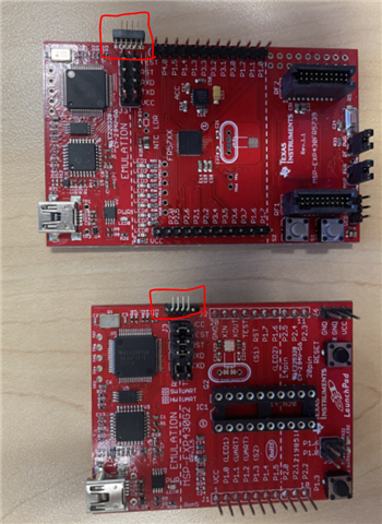
If using the MSP-EXP430FR5969:
You will need to remove the IC from the LaunchPad. This disconnects the MSP430FR5969 so that it is not the target device anymore, since the TST/RST/V+ pins connect to the 50-mil header even if the jumpers are removed from the bridge. Once the IC is removed, connect the GND, V+, RST, and TST jumpers on the jumper bridge to provide power and connect the eZ-FET debug signals of the MCU to the 50-mil header.
If using the MSP-EXP430FR5739:
Remove the 3V3, GND, SBWTDIO, and SBWTCK jumpers on the jumper bridge to disconnect power and the eZ-FET debug signals from the MSP430FR5739. This will force the power and SPI-by-wire pins to connect the 50-mil header instead.
2) Once the connector is mated to the LP, plug in the connector to the 4-pin SPI-by-wire female connector that is on the left side of the DRV8343x-EVM in the following manner (tops of boards face up). This connects the eZ-FET debug probe from the MSP LaunchPad to the MSP430F5529 onboard the EVM so that CCS will recognize the MSP430F5529 as the target device. 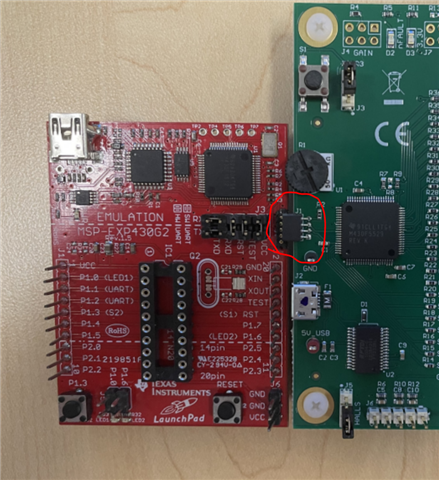
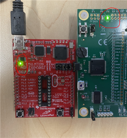
3) Once connected, plug in a micro-USB cable into the LaunchPad and the 3.3V LEDs should light up on the LP and on the EVM.
4) At this point, you should be able to flash the sensored trapezoidal, sensorless trapezoidal, or independent mode firmware onto the MSP430F5529 MCU. For steps how to download CCS and flash the program, follow Section 3 of this document. Note, if using the most revision of Code Composer Studio, the project may not configure the target automatically with the latest compiler version. Right-click the project in the Project Explorer and click on "Properties". Check "Manage the project's target-configuration automatically" as shown below. Click Apply and Close. After a successful "Build" of the project, click "Debug". If the project requires a compiler update, a pop-up will appear. Click Accept and continue until the project successful flashes the project to the MSP430F5529. 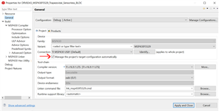
5) Once the program is flashed to the MSP430F5529, stop the debug session. Power on the DRV8343x-Q1EVM and plug in the Micro-USB cable to the EVM. Launch the DRV8343-Q1 EVM GUI and select the variant of DRV8343-Q1 used. On the next window, the firmware flashed onto the MCU will automatically appear as the control type (i.e Sensorless Control). To use different control methods, you will need to follow the steps above to flash the required firmware onto the MCU before running the GUI (i.e Sensored Trapezoidal, Sensorless Trapezoidal, or Independent Mode).
