This thread has been locked.

If you have a related question, please click the "Ask a related question" button in the top right corner. The newly created question will be automatically linked to this question.

DRV2624: some of the watches vibration issue

Part Number: DRV2624

Hi team,

After DRV2624YFFR motor drive is calibrated at F0, some watches will vibrate after hard restart of the watch.

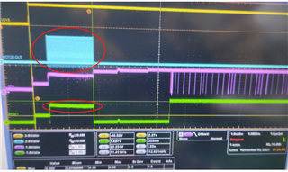
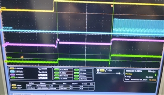
From the quantitative waveform, I2C has no communication, and the chip is not fully up, the motor vibrates by itself.

This problem related to the motor were discovered during the mass production process. After the TI chip is calibrated, it is found that the motor has regular vibration and short-term vibration when it is turned on. The normal state should be no vibration.

Phenomenon 1: Before the motor is calibrated, the driver IC of AW vibrates when it is turned on, and the driver IC of TI not vibrates when it is turned on.

Phenomenon 2: After the motor is calibrated, AW did not find any vibration when starting up. TI has found that 7pcs machines must vibrate when starting up, and some are long vibrations and some are short vibrations.

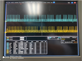
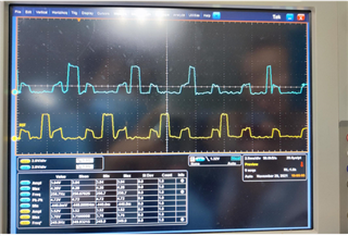
The figure below shows the vibration waveform and the waveform of the flying wire of the motor shrapnel when the machine is turned on.

The customer would like to know what's the possible reason for the vibration.  Could you help check this case?

Thanks and Best Regards,

Cherry

  • Hello,

    Are the two chips on PCB at same time? or is one only placed on a single PCB as to avoid interference?

    Also what is status of the the trig and rst pins I see them possibly being pulled up? 

    Best Regards

    Carson

    LPA Applications Engineer

  • Hi Carson,

    Thanks for your support!

    And the updates are as follows:

    The calibration is configured with 0x07 register to be = 3 and set go bit, 1 at normal vibration and 0 at end of vibration. Suspect re-configuring 3 after calibration. The customer verifies that the hard restart still vibrates after clicking on the vibration and stopping in the finished mold.

    Reset and TRIG/INTZ have a high voltage when power up, which corresponds to vibration. Checking the spec, TRIG/INTZ can trigger a vibration, is there any way to not use this feature?

    The main chip cannot stabilize the high portion of reset and TRIG/INTZ when power up, the high portion corresponds to the vibration waveform.

    Are the two chips on PCB at same time? or is one only placed on a single PCB as to avoid interference?

    There is only one placed on a single PCB, which is pin to pin.  And the pcb package is stacked together.

    Also what is status of the the trig and rst pins I see them possibly being pulled up? 

    Yes, they are both be pulled up, may because the main chip has not fully up and is being charged from I2c when it is powered up.

    Thanks and Best Regards,

    Cherry

  • Hey Cherry,

    If those lines are pulled high it creates Hi-Z state during start-up which will randomly trigger that vibration and there is no way to disable trigger functionality without starting it up, and even then once you reset you will have same problem. You will need to remove the pull-ups.

    This is because DRV pins have pull-downs which creates a conflicting Hi-Z state on start up.

    Best Regards,

    Carson

  • Hi Carson,

    Thanks for your reply! The point is, the customer did not use the external pull-ups, this problem is caused by the main chip being powered from I2C when it is powered up. Could you help check the possible reason? 

    Thanks and Best Regards,

    Cherry

  • Hi Cherry

    Sorry for the wait

    What is driving the pins? The MCU directly? if so do its pins have any pull-ups or downs?

    Best Regards,

    Carson