This thread has been locked.

If you have a related question, please click the "Ask a related question" button in the top right corner. The newly created question will be automatically linked to this question.

BOOSTXL-DRV8304H: Question about strange current measurement.

Part Number: BOOSTXL-DRV8304H
Other Parts Discussed in Thread: DRV8304,

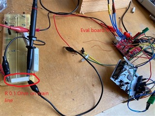
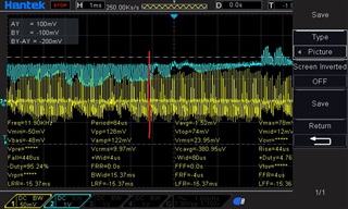
Hello, I have a question about a strange behavior in current measurement. I use on the main line of the supply a shunt resistor with 0.1 ohm, this is the yellow line on the osciloscopes's screen. 

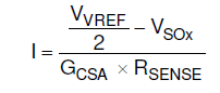
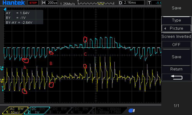
With the blue line is the SOx output of the DRV8304H. As you can see on the red line the voltage drop on the shunt resistor is 50 mV, that means I=V/R=50mV/0.1Ohmn= 500 mA 

The SOx Pin output voltage is 1V and that means 10 A current. I assume that BOOSTXL board is configured to used 10x Gain. So I cannot explain why I measure 500mA Current but DRV8304 delivers a measurment of 10A. That is strange to me and my software cannot run correctly. 

This is the implementation of my software to calculate the current, In my case 1V = 1241 ADC Raw Value. 

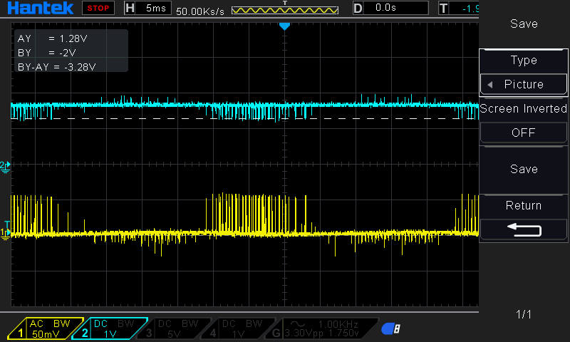
An other Problem is when I disconnect the motor and I use PWM3x with 50% duty cycle then I have the following output on the SOx. Osciloscope is on AC Decoupling, SOx is the blue color. This noise has as result in the software to 'see' about 1A on the peeks, although the motor is disconnected and the setup is on motor stop configuration. 


Could you help me? Because I think I have wrong data from the IC and my software cannot run properly. 

Appreciatively,

Nikos

  • Hi Nikos,

    Good to hear from you again. 

    DRV8304 uses output offset bias from VREF/2 if you're configured for bidirectional mode (default of DRV8304H). 

    Use this equation to calculate current from SOx:


    So if VSOx = 1V and VREF = 3.3V,, then I = (1.65V - 1V)/(10V/V *  0.1) = 650mA. Make sure you calibrate the CSAs with the CAL pin before running the algorithm, and that the MCU samples the SOx outputs after the CSA setting time. Sampling at the SOx outputs when they switch before the SOx outputs settle can cause overestimation, whereas sampling at the SOx outputs too late can cause underestimation of the phase current. A low pass RC output filter at  the SOx output is useful as well for filtering out high frequency noise; choosing a cutoff frequency of ~1MHz and placing the RC filter near the MCU's ADC pin. 

    Is there similar noise seen at VREF? Does the SOx trace run near any high frequency signals, such as SPI connections?

    Thanks,
    Aaron


  • Hi Aaron, 

    Thank you for your reply, cause of Corona I was six months off. And I have started to work again with my Motor after a long time. 

    So about my topic, I think you did not understand my issue correctly :). I have changed to a  BOOSTXL-DRV8304H device. 

    I don't use a 0.1 Shunt resistor on the DRV but I use the embedded 0.007 Ohm resistors. In your equation and in your calculation, if you change the resistor value to 0.007 ohm then you can see that the result is ~9 to 10 Amperes. Also if you see my Simulink model on the screenshot, then you can see that I have implemented correctly the same equation as mentioned in the datasheet of the drv8304.

    So my issue still exists. 

    About the second issue, because I use the BOOSTXL-DRV8304H and I have seen that you have integrated a low pass filter. So still I cannot explain this behavior and also I do not use the SPI bus. 

    thanks,

    Nikos

  • Hi Nikos,

    • to follow-up on Aaron's earlier comment, can you try running the "AUTOCAL' procedure for this device, as described by the datasheet, so that we can see if this is calibration error causing the incorrect CSA output value?
      • datasheet section below: 
    • Also, for the BOOSTXL-DRV8304H + MSP430F5529XL LaunchPad configuration, 
      • how are you providing power to the system? 
      • Usually the boosterpack is plugged on top of the launchpad, as the header pins are mapped to work between those two PCBs. 
      • In the case where you are seeing some strange noise on the waveforms, I just want to make sure we don't have situation where there are multiple redundant power supplies fighting eachother and causing noise in the overall system. 
      • May want to review the EVM user guide to check if all the jumpers and etc on the PCBs are set up as instructed

    Thanks and Best Regards,
    Andrew

  • Hi Andrew, thanks to Aaron and to you for your help.

    First of all, I use a battery 10 Volt for the DRV and a usb source for the controller.

    I tried to implement your suggestion about the calibration so I implemented the following pseudo algorithm.

    Connect CAL Pin to Output pin.

    set CAL Pin to low after reset.

    In init phase, set CAL to HIGH and read ISENx. Subtract from 2048 Value the measured value and save it in the global variable CalxVar.

    Subtract in every ISENx measurement the value from the global variable CalxVar.

    BUT I did not see something better in the software behaviour. Still illogical measurements.

    So I decided and soldered on the Shunt Resistors 2 cables, like the picture and I make with the oscilloscope a measurement.

    So I have some point to discuss.

    Yellow is the channel on the shunt resistor and the blue is the ISENB pin.

    Point A.

    -50mV on yellow => I =V/R=-50mV/0.007ohm=-7.1 Amp

    600mV on blue => I = (1.65-0.6)/(10x0.007) = 15 Amp

    Point B.

    -20mV on yellow => I =V/R = -20mV/0.007ohm=-2.58 Amp

    1.25 V on blue => I = (1.65-1.25)/(10x0.007) = 5.71 Amp

    Point C.

    50 mv on yellow => I = V/R=7.1 Amp

    2.20V on blue => I= (1.65-2.20)/(10x0.007) = -7.85

    As you can see there is no a correct relationship between Rsense and ISENB, I am afraid that I read random numbers on ISENx pin. 

    Could you help me to fix it?

  • Hi Nikos,

    Thanks for the follow-up 

    Please give me a day or two to review this info further and see if there are some other suggestions we can provide 

    Best Regards,
    Andrew

  • Hi Nikos,

    Just giving a heads up that I need a few more days to brainstorm ideas for root cause and respond to this e2e post - 

    Will keep you updated 

    Best Regards,
    Andrew

  • Hello Andrew, 

    do you have news for me? 

    best regards, 

    Nikos

  • Hi Nikos,

    Still looking into this but will follow up with a response by today or early next week at latest 

    Best Regards,
    Andrew

  • Hi Nikos, 

    Thanks for your patience on this matter - I did get a chance to review the information further. Please see inputs below.

    • the experiment data you provided with measuring the voltage drop across Rshunt vs the SOx/ISENx voltage was very helpful 

    Reviewing some of the communicated information mentioned earlier, confirmed a few details by checking the device datasheet and EVM hardware user guide documents: 

    • Rshunt on the DRV8340H is 0.007 Ohms according to the EVM schematic 
    • Gain setting has a 47kOhm resistor to Gnd, which corresponds to a CSA gain of 10V/V
    • Hardware 'H" version EVM operates on bidirectional CSA mode, so the intended relationship between variables is indeed supposed to be defined by Equation 3 in the datasheet: 

    Based on the above information,

    • it does seem like there is a problem with the BOOSTXL-DRV8304H CSA result 
    • If VREF = 3.3V as suggested, 
    • and if AUTOCAL routine was done properly,
      • (this looks like it's the case, since the DC offset of the blue ISENx waveform is centered around 1.65V it seems -> which would correspond to a zero-crossing point of I=0A when VSOx and VREF/2 cancel each other out. 

    I am not sure what other explanation there might be for the CSA output values under these circumstances. 

    • Will discuss with the team again tomorrow during our weekly meeting to see if there are any explanations for why this behavior is not as expected 

    Thanks and Best Regards,
    Andrew

  • Thank you Andrew for your reply, I am waiting for your solution so I could go on with my work.

    I made today some extra measurements.

    I used a rheostat instead of a motor, I set up on 1.6 Ohm and I made the same measurements. My configuration looks like this.

    And my measurement  looks like the following pic.

    I have 12 Volt supply, so with 1.6 Ohm Resistor, I am waiting 7,5 Amperes.

    If I calculate the current according the yellow line then I see I= 55mV/7mOhm = 7.8 Amperes

    If I calculate according ISENB with 1.28 V then I have I = 1.65-1.28 / (10 * 0.007) = 5.2 Amperes

    So there is a significant offset between the measurements.

    Best Regards,
    Nikos

  • Hi Nikos, 

    Thanks for the follow-up - I did get a chance to discuss this e2e thread's CSA issue with a few of my colleagues, and have the feedback below on next steps to investigate: 

    The next steps for debug will be to review the CSA electrical characteristics parameters on pages 8,9 of the datasheet and see if it may explain some of the results observed

    • Can you try some different VREF input voltage settings (maybe 5V to see if the results change/improve in the system's CSA performance?
    • may need to simplify the CSA operation condition a bit further to help remove some other variables like CSA settling time 
      • e.g. applying DC voltage bias across SPx/SNx without motor connected, to see if the CSA responds normally to DC-level inputs
    • temperature drift
    • confirming if scope measurement across the sense resistor has the right polarity 

    Other than steps above, I am not sure what other explanations there would be for the CSA behavior reported

    • has it just been this one board that has the problem? Or do you possibly have a second copy of the board on hand to see if the results are reproducible on a second setup 

    Best Regards,
    Andrew 

  • Hi Andrew, 

    thank you for your reply. I did not have a second Eval Board, only one. Did you try to see in your labor if you have the same behavior or this problem exist only in my case? 

    Also what did you mean with CSA? Which PIN? 

    Thanks, 

    Nikos

  • Hi Nikos,

    With the CSA Current Shunt Amplifiers, 

    • the main remaining suspicions on the CSA outputs not matching the supposed inputs would be the settling time of the measurement 
    • in your system, because the shunt resistor voltage is frequently changing, this CSA settling time could be possibly not sampling the voltage at the right time (when the settling time has passed and the voltage on the CSA output is more likely to reflect the present voltage on the sense resistor) 
      • one way to debug further is to have the shunt resistor voltage maintain a stable DC voltage bias, and then see if the CSA output has a better performance and starts outputting more accurate values. This would eliminate the impact of 'settling time' 

    As for replicating the test results on our local bench, I will follow up with the team to see if I can locate one of these DRV8304H EVM boards for hands-on debug. My bandwidth is currently a bit limited due to the many ongoing customer debugs, so this may take some time for me to replicate locally 

    Thanks and Best Regards,
    Andrew 

  • Hm, very complicated. If the CSA cannot sampling the current so fast, then I cannot use it for my project. Or I have to buy an other board if my is defect.

  • Hi Andrew again, 

    If you can send me a sample of the Eval Board, then I can test it again and then I will send the sample back to you.

    I was before some months in contact with Reingen, Tobias for samples. 

    Thanks and Best Regards,
    Nikos

  • Hi Nikos, 

    Understood, and let me sync up with the team on this to see what can be done - and what might be the best way to resolve this issue 

    Will try to get a response on what the plan is for this by early next week at latest

    Thanks and Best Regards,
    Andrew 

  • Hi Nikos,

    One other thing - can you let me know if this behavior also occurs on the other two phases' CSA? 

    It will be helpful to know whether this might be a case with just one impacted CSA, or if there's a more widespread problem on the board's DRV chip that affects all 3 CSAs systematically 

    Best Regards,
    Andrew

  • Hi Andrew, the A Channel seems to work correctly, if I make the calculation, then it seems to be exactly the same amperes.

    I will try later to test C channel and if it works, then maybe I can change my set up to use A-C as inputs for the FOC. 

  • Thanks Nikos,

    Appreciated on your help in checking the other phases - 

    It makes the possibility of a phase-specific defect more likely as a result, considering that all 3 CSA's on the DRV devices are normally treated the same and should produce similar results. 

    Best Regards,
    Andrew

  • Hi, just tested Phase 3, It seems to be also defect. The ISENC Pin does not deliver the same amperes as seen on the shunt resistor. A very big offset is presence.

  • Hi Nikos, 

    Thanks for sharing the results with such quick turnaround time - 

    I'll send an email message and cc Tobias Reingen. 

    Ultimately for the next step of the debug, I think we'll have to work on getting a second EVM (or a possibly a replacement DRV8304H device to solder onto the existing EVM) in order to see if we can reproduce the issue. 

    Best Regards, 
    Andrew

  • Hi Andrew.

    I de-solder all the components from the filter on ISENX and I think now is working correctly.

    I used also a home made LPF on SOx and I can see a negative effect or simply a loose of precision. I think LPF has negative impact on precision.

  • Hi Nikos, 

    Glad to hear that the root cause has been found! 

    Will take note of this result in case any other customers encounter the same issue with this EVM. 

    For the CSA output on ISENx, the guidance that we usually give from the system side is that the cutoff frequency of the CSA output should be approx 10x larger than your expected maximum switching frequency and placed as close as possible to your MCU inputs receiving the CSA signals.

    That way, it can filter out the high frequency noise without directly impacting the CSA signal expected at the MOSFET switching frequency 

    Thanks and Best Regards,
    Andrew

  • Hi Andrew,

    I use 20 KHZ PWM so your LPF is configured about 1MHz. That means your requirement for 10x pwm freq for the filter has been satisfied but still the measurements are not accurate.

    Maybe you have to review this requirement again?

  • Hi Nikos, 

    Understood and thanks for the follow-up -

    We will keep this in observation in mind and discuss within the team. 

    Will follow up if I hear any information that may be useful to share 

    Best Regards, 
    Andrew