


Choosing the right system architecture for a Brushless DC (BLDC) motor system can be overwhelming. This FAQ will help you pick what type of system architecture is best suited for your application. TI offers several devices within each architecture across a wide range of power levels. The PCB in Figure 1 shows the four different architectures that the TI brushless DC (BLDC) solution offers. Choice of system architecture depends upon the available board size and motor power requirements in a given application.
The four architectures are as follows:
- Gate driver – Needs an external MCU for motor commutation control & external MOSFETs on board to drive the motor
- Gate driver with integrated motor control – Needs external MOSFETs on board to drive motor
- Motor driver with Integrated MOSFETs – Needs an external MCU on board for motor control
- Motor driver with Integrated MOSFETs & motor control – No external MCU or MOSFETs needed on board to drive motor
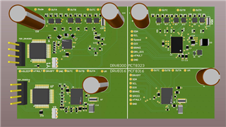
Figure 1 – Architecture Size Comparison
Integrated FET vs Gate Driver Architecture
Each architecture has its own advantages and disadvantages. For example, the MCF8316A used in architecture 4 has the smallest footprint of the four architectures shown above since the control, driver, and MOSFETS are integrated in the device. These devices are limited in terms of power due to power dissipation in the package, so they are best suitable for low-power applications. Integrated FET devices also minimizes the bill of materials (BOM) which reduces the board space a motor drive solution will occupy. The TI portfolio offers a wide range of integrated drivers with varied power delivery capabilities up to 100-W and over 8-A peak current. For more information, please visit our TI precision labs video HERE.
A gate driver's purpose is to switch external FETs to control current flow through a motor. Since the driver can be isolated from its power stage, high-voltage and high-current applications are more attainable using these parts. As a rule of thumb, if a system will have over 70-W of output power, it is suggested to use a gate driver device. TI’s portfolio offers a wide range of gate drivers equipped with technologies such as Smart Gate Drive to simplify driving MOSFET gates and protect gate drivers from abnormal conditions. A smart gate driver allows for system designers to adjust drive parameters, such as the gate voltage slew rate without board modifications.
Integrated Control vs External Control Architecture
TI’s MCx devices, used in architecture 2 and 4 in example above, offer the flexibility of having an integrated motor control algorithm along with the driver. This allows the user to implement a code-free solution with motor control options that are configurable and easy to tune. For instance, in the case of the MCT8316Z, the device also integrates three analog hall comparators for position sensing to achieve sensored trapezoidal BLDC motor control. This allows systems designers to reduce software overhead. On the other hand, one benefit of using an external microcontroller for motor commutation is that the system designers can have flexibility to add their own logic for motor and system control. Examples of system control is if the designer wants to commutate a motor with 6 PWM signals rather than 3 or 1 PWM signals, light up an LED after deducing a specific type of fault (such as a temperature warning), or configuring device-specific settings over SPI.
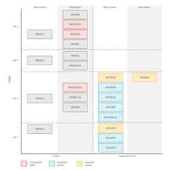
Figure 2 – Portfolio of Devices by Voltage
TI’s BLDC solutions offer a wide range of architectures across voltage and power levels. A snapshot of featured products can be seen in Figure 2. For additional help with selecting the right device for your application, you can refer to “Brushless – DC Motor Driver Considerations and Selection Guide”
