This thread has been locked.

If you have a related question, please click the "Ask a related question" button in the top right corner. The newly created question will be automatically linked to this question.

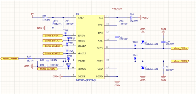
DRV8874-Q1: The current output pin IPROPI conversions to the motor current, and the measured results are quite different from the conversion results.

Part Number: DRV8874-Q1

The circuit designed according to the current detection in the manual is also calculated according to the corresponding formula. The current situation is that the measured results do not correspond to those calculated by the formula.

At present, the chip is configured as PWM control mode, IN2 is set as low level, IN1 is driven by 20kHz and 60% duty cycle, RIPROPI= 1K, and the measured VIPROPI = 0.044v. According to the formula, the converted current is 97.78ma, but the motor current detected by the actual ammeter is 48.7mA.

The motor current and VIPROPI voltage under 50% ~ 100% PWM drive are measured. The formula conversion does not correspond to the actual measured current.

What's the reason?
  • Delmore,

    It appears that you are going between a drive state and a coast state (IN1=IN2=0V).  There is a truth table in the data sheet.  In the coast state, there is no reporting on the IpropI output.

    See the following section in the data sheet:

    7.3.3.1 Current Sensing

    Normally when driving a brushed motor, you would switch between slow decay (low-side recirculation) and the drive state.  To accomplish this, you can set IN2 = 1 and PWM IN1.  This will ensure that current always flows thru a low-side FET and properly reported on iPropi during drive and recirculation states.

    Regards,

    Ryan