This thread has been locked.

If you have a related question, please click the "Ask a related question" button in the top right corner. The newly created question will be automatically linked to this question.

DRV8824: PCB Layout line width issue

Part Number: DRV8824

Hi team,

Here's an issue from the customer may need your help:

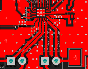
The DRV8824 is used to drive a two-phase stepper motor using the VQFN package, which is a 0.2-mm to 0.3-mm pin width for OUTA and OUTB, so the PCB line width is limited to within 0.3-mm for PCB layout. While the motor set current is 1.8 A RMS and the PCB copper thickness is 0.5 oz, this current is used for a line width of 0.3 mm. Will this way have any bad impact and could you give some recommendations for layout?

Could you help resolve this case? Thanks.

Best Regards,

Cherry

  • Hi Cherry,

    The width of the pins are design to be able to carry the maximum current rated for this device. However, the width of the PCB trace for the outputs should be increased to lower the resistance and allow for better thermal performance. Below is an example layout.