


In some applications, it is important to know when a motor stalls due to an obstruction or reaching the end of travel (for example a door lock reaching the final locked position). This FAQ will discuss a sensor-less approach of stall detection by using the current sensing information from the DRV8251A. However, this technique can also be replicated on any motor driver with current sensing capability.
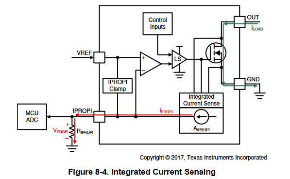
The DRV8251A uses a current mirror to monitor the motor current. The current is scaled down by the current mirror circuit which is fed to an external resistor (R_IPROPI) generating a voltage proportional to the motor current (V_IPROPI). The figure below shows a block diagram of the IPROPI current regulation circuit. The IPROPI voltage (V_IPROPI) is connected to an ADC of a microcontroller which can be monitored. Because the motor stall current is much larger than the typical operating current, one can program the MCU to detect the large stall current and take action, such as disabling the driver.
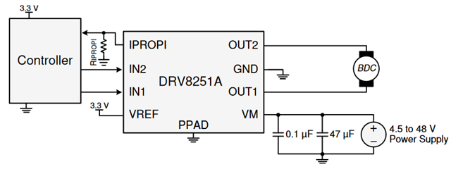
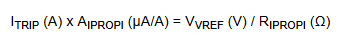
For this example, I will be using the DRV8251AEVM, which is the evaluation board for the DRV8251A motor driver IC and has integrated current regulation. The diagram below shows a simplified schematic. In this example, the IPROPI pin is connected to an ADC channel of a micro-controller. The RIPROPI resistor and VREF voltage sets the current regulation limit (I_TRIP) based on the equation below. IPROPI is a fixed value so adjusting VREF changes the I_TRIP limit value.
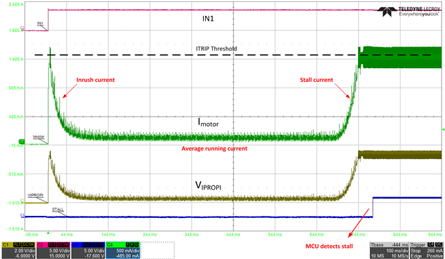
The diagram below shows how current sensing is used to detect when motor stalls. IN1 and IN2 are the control signals of the driver. IN1 is set HIGH to enable the motor, then IN1 is set LOW once the stall is detected. Although in this example the outputs are disabled once the stall is detected, the hardware designer can implement other stall detection responses such as reverse motor direction, blink an LED, display an error message, etc.
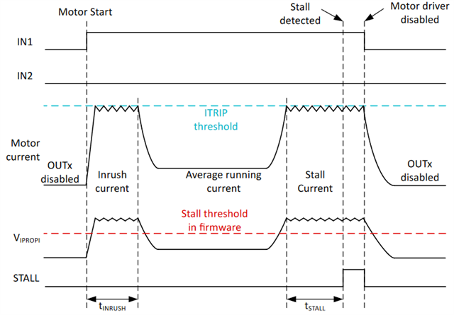
The example waveform also shows that the motor current is limited to the ITRIP threshold. The initial inrush and stall current are being limited to ITRIP threshold which is set by the VREF and RIPROPI values. This stall detection scheme does not require ITRIP current limiting to be used, but it can help reduce large inrush and stall currents in the system.
The stall threshold is set in the microcontroller firmware. The RIPROPI resistor should be chosen so that the range of VIPROPI is within the dynamic range of the ADC input. The stall threshold may need to be obtained experimentally, so that it is below the ADC value of the current at the ITRIP threshold but above the ADC value of the average running current.
The firmware needs to have a way to differentiate the inrush current from a stall event. The inrush current at motor startup is larger than the nominal current of the motor due to the higher torque required to get the motor up to speed. One way to do distinguish inrush current from a stall event is to ignore the ADC above the stall threshold for a certain amount of time (t_INRUSH) when the microcontroller initially actuates the motor. Since the STALL threshold needs to be higher than the nominal motor current, the inrush current will typically be above the STALL threshold.
After the t_INRUSH time elapses, the firmware can indicate a stall whenever the ADC values representing the motor current are above the stall threshold. However, some systems may choose to operate at these high currents for a longer period of time to try to push through a stall condition. To implement this, the system designer can add a stall delay time, or t_STALL to drive at the high currents for a longer period of time before taking action.
On the DRV8251AEVM, there is a dedicated red LED connected to an I/O of the MCU to indicate stall. The MCU is programmed to turn on the LED and pulling control signals LOW when a stall is detected. Depending on your application needs, the MCU can be programmed to perform any desired action. Typical response methods to a stall include indication only (having a visual LED indicator turning on but motor operation continues), disabling outputs (disabling driver outputs to stop motor until the driver is reset manually or via firmware), and reversing direction (inversing the control logic to reverse the motor direction).
The waveform below was taken using a modified DRV8251AEVM board and a 12-V brushed DC motor. In this example, no action was taken when the stall was detected. However, disabling the outputs when a stall is detected can protect the motor and the system from excess mechanical forces and electrical currents caused by stalling. In the waveform, you can observe how the initial inrush current was ignored by the MCU. This is because the stall delay programmed is longer than the inrush time. To ensure the stall detection is reliable and consistent, it is recommended to make the stall delay at least 1.5 times the inrush time. However, keep in mind that the stall delay and stall threshold are only tuned for a specific motor and may need to be adjusted for other motors with significantly different parameters and operating conditions.
In the example above, the integrated current sensing architecture is used for the implementation of stall detection. The external current sense architecture is another method for sensing current. It relies on a power sense resistor either in the low-side, high-side, or in-line with the H-bridge. You can visit the following resources listed below to learn more about various current sensing architectures and stall detection design examples:
- Current sensing and current regulation
- Section 9.2.2 of DRV8231A datasheet
- Section 9.2.2 of DRV8231 datasheet
- Operating an Engine-Grille Shutter Motor App-note
To conclude, this sensorless stall detection method is a simple yet reliable way to detect when a motor stalls due to an obstruction or reaching its end of line travel. Since this method relies on monitoring the current sense output voltage with an MCU, extra MCU and firmware resources will be required for complete implementation. Furthermore, the stall threshold level and stall delay time may be different from motor to motor. These variables need to be experimentally measured for each motor.
