Hi team
Here's some issues from the customer may need your help:
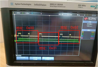
1. Using the MCU's port, simulate the spi and see through the oscilloscope that the analogue spi transmit configuration drv8705 data was successful. The parameters are as follows:
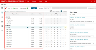
A. Configuring the IC_CTRL Register: 0x0436
B. Configuring the BRG_CTRL Register: 0x0540
C. Configuring DRV_CTRL_1 Register: 0x0677
D. Configuring DRV_CTRL_2 Register: 0x0777
E. Configure DRV_CTRL_3 Register: 0x0804
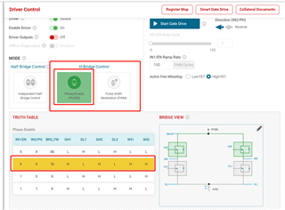
2. The IN1/EN configured for the drv8705 is the PWM input, the IN2/PH is the I/O input, and the positive reversal of the motor is controlled by the high and low levels.
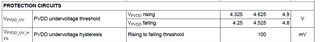
3.Configure the DRVOFF and SLEEP pins of the drv8705 high.
Note: using PH/EN H-Bridge Control (BRG_MODE = 01b or MODE = Level 2)
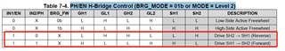
Issue: After configurating as above, IN1? En and IN2/PH, output good, but GH1, GH2 output high, GL1, The GL2 outputs are low, SH1 is high, and SH2 is high.
Could you help check this case? Thanks.
Best Regards,
Cherry