Other Parts Discussed in Thread: , DRV8320
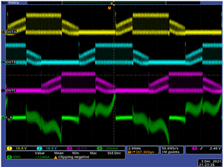
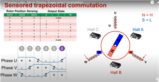
I'm setting up for a commutation exercise, and I'm doing trapezoidal commutation, where I want to be alternating/switching my half-bridges to be either PWM driven, Hi-Z, or GND. So depending on trapezoidal stage, I'm either setting one of the 3 phases to voltage based on my generated PWM, or I want to set to to ground, or leave Hi-Z for back EMF measurement...
When I'm in PWM stage for a particular phase, I switch a GPIO mux to PWM mode, and I verified that PWM is correct - measured on the board I/O pins, frequency right, and DC adjustment works all as expected.
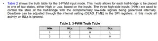
I'm not however sure if I'm setting correctly the GIO, especially when I want a phase output to be ground.
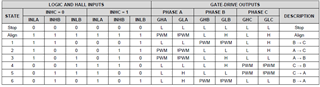
Looking at this table in the data-sheet for DRV8305:
As I understand, there are 2 Hi-Z states, and I'm settings inputs as : (0, 0) when I need phase to be Hi-Z; or switching GIO mux to PWM if my phase is in PWM stage;
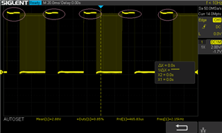
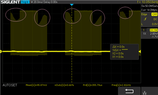
and I then I need ground on the phase, and I'm using (1,0), but I don't fully understand especially what I see on the phase.
I sort of expect 0V when its on ground always when it's on ground, and PWM duty cycle is 0, but that's not what I see , I see a square wave at the frequency of my commutation.