This thread has been locked.

If you have a related question, please click the "Ask a related question" button in the top right corner. The newly created question will be automatically linked to this question.

DRV11873: DRV11873 power on sequence

Part Number: DRV11873
Other Parts Discussed in Thread: DRV10983,

Dear Sir/Ms.

We have customers who use DRV10983 to design fans, and the terminal has defective products. It was found that PIN12 (5V) and PIN16 (PWMIN) were burned.
The customer asked the PWM signal to the fan before the 12V power supply, is this OK?
The fan PWM signal continues to give the signal, and then the 12V power supply is supplied to the fan. Is there any problem?

Simulate the usage environment of the end customer:

The PWM of the MCU is connected to the fan, but there is a need to plug and unplug the power cable to measure the signal voltage waveform of the PWM terminal of the fan. PMWIN PIN found the following waveform.

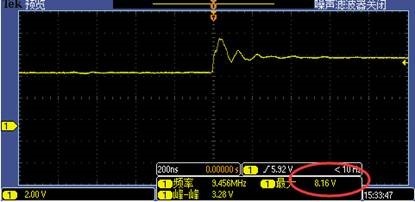
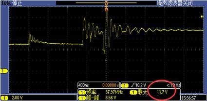
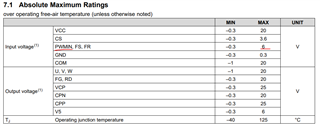
The original 5V voltage of PWM has measured abnormally high voltages of 8.16V and 11.7V.
Is it the main reason for the exception?


If this power-on sequence of DRV11873 is abnormal. And PWMIN will have a voltage higher than 5V, what is a reasonable explanation to convince end customers? 

Is there any reasonable explanation for the end customer to understand that this is an abnormal power-up sequence?

Best Regards,

Kami Huang

  • Hello Kami,

    Thank your for your questions and for posting to the MD forum. The datasheet indicates that the max rating of the PWM_IN pin should not be above 6V, so the 8.16V and 11.7V that are being experienced on that pin violate the absolute max specs damaging the device (image of datasheet below). The reason the customer is also seeing damage on the 5V regulator pin is because internally the PWM_IN pin is pulled up to V5 internally

    My thoughts on what could be occurring would be the following: This device once provided with a PWM signal will startup the motor with 100% duty cycle until it generates enough BEMF (takes 4 zero crossings) once this occurs the device will enter closed loop control and will go into the commanded speed based on the PWM input. If the commanded speed is slow there could be voltage that is generated and pumped back into the supply from the motor. If the VCC goes over the recommended specs then perhaps this could damage the 5V LDO and hence why were are seeing larger voltages on the PWM_IN pin. If the VCC could be monitored then this might give us a good indicator if the motor is pumping up the voltage beyond recommended specs we could also monitor V5 to see if it is getting a spike similar to PWM_IN and FG to see if this device is entering closed loop as well. 

    These waveforms might give us a better indicator of what is going on. As of now all we know is that the voltage on PWM pin is being violated which is most likely affecting the 5V LDO as well. 

    Best,

    Isaac