This thread has been locked.

If you have a related question, please click the "Ask a related question" button in the top right corner. The newly created question will be automatically linked to this question.

DRV8833: Automatic engine speed control

Part Number: DRV8833
Other Parts Discussed in Thread: DRV8830, DRV8832

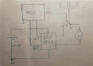
Hello. I am using DRV8833 for low voltage motor. In my circuit, I only use the reverse. I don't use PWM. Now I have a question about keeping the engine speed constant. It's like old cassette recorders. It used an electronic circuit of constant revolutions. Are there similar microcircuits in the catalog. Importantly, it is powered by a 4 volt lithium battery. There is a very old chip TDA7274. Perhaps there is something modern at TI.

  • Hi Igor,

    The DRV8830 is a good option. As stated in the datasheet:

    The DRV8830 provides the ability to regulate the voltage applied to the motor winding. This feature allows
    constant motor speed to be maintained even when operating from a varying supply voltage such as a
    discharging battery

    This device will allow you to maintain constant motor speed by regulating the voltage at the terminals of the motor.

  • Thank you very much for your reply. I have studied DRV8830. A very interesting option. But unfortunately, it requires an additional two outputs from the microcontroller. And I don't like the price and availability. But you gave me a very good idea. And I found with your help an option  DRV8832. There you can adjust the speed with a simple resistor at Vref. Now I'm worried about whether the engine speed will be constant, or such regulation will not be enough. I need to maintain constant speed regardless of the amount of load on the engine. How do you think? In this case  DRV8830, we have a constant current, in this  DRV8832 constant voltage.Thanks a lot.

  • Hi Igor,

    The DRV8832 will also be a good option. It has voltage regulation similar to the DRV8830 but simpler pinout.

    Now I'm worried about whether the engine speed will be constant, or such regulation will not be enough

    The voltage regulation adjust the PWM duty cycle at the output terminals to maintain a constant average DC voltage. This will help maintain the same motor speed. However, since there will be varying loads on the motor, it won't be able to maintain the speed. When the the load on the motor increases, the motor speed will reduce and the PWM duty cycle will need to be increased to maintain the speed. Therefore, a closed loop system will be required. This article gives a suggestion for sensorless motor speed control: Easy cruise control for brushed motors using BEMF. The drawback to this solution is requiring more MCU resources.

    Please read the article and let me know if this a solution you can implement in your design.

  • Thanks Pablo. This is a brilliant answer. You understand the problem that worries me. This is a very original idea. It is impossible to change the main controller in my scheme, so I will do from what I have. Now I am trying to decide how to make "K" solid state. The drv8833 has a lower transistor on the negative bus (I removed the R sense), so the ADS should work correctly. I'll make a prototype and tell you how it turned out. Thanks again Pablo, you have a very great experience.

  • Hi Igor,

    I'm glad you found the app-note useful.

    I'm having some difficulty understanding your design. What exactly is the "K" solid state? It looks like some sort of switch or relay. Can you provide some clarification?

    I'm also curious as to why you decided to go with the DRV8833? This is a dual H-bridge device but you will only be driving one motor. Is it mainly due to the low RDSon?

  • Good afternoon, Pablo. K is the key. It will switch at the command of the microcontroller from engine mode to generator mode. At the moment when the generator mode, the microcontroller will turn on the ADC. Unfortunately, I gave up on this option. This requires an additional wire and takes away the resources of the microcontroller. In the meantime, I'm back to the good old analog way. I plan to put the LA5527 chip in front of the 8833, it has good capabilities. Its drawback is that it has been discontinued and is not available. I also ordered a similar AN6652, I'll check it in work.
    I used the 8833 because I needed a low voltage, low dropout driver for reversing only. I did not use PWM modulation. It is, of course, redundant, but with one built-in driver, I did not find it. If you can advise, I will be very grateful.
    Thanks again for the advice. It opened up opportunities, and I will definitely take advantage of them next time.

  • Igor,

    It is a US holiday today.  Expect a response tomorrow.

    Regards,

    Ryan

  • Hi Igor,

    Thanks for the explanation.

    I did not use PWM modulation. It is, of course, redundant, but with one built-in driver, I did not find it. If you can advise, I will be very grateful.

    Can you give more clarification on your requirements? Are you planning on controlling at 100% duty cycle? I'm a little confused by your statement above. I can recommend another device that best meets your design criteria.

  • Are you planning on controlling at 100% duty cycle?  Yes, that's right, only yes / no, forward / backward. And would be grateful for advice. 

  • Igor,

    The solution that is shown on the app-note relies on constant adjustment of the control signal duty cycle to maintain speed. If driving at 100%, the voltage needs to be regulated to maintain speed. This is where devices like the DRV8830/32 that are capable of regulating the output voltage will help. However, due to the varying load is your system, voltage regulation alone will not be sufficient. You'll need a closed loop control system.

    I plan to put the LA5527 chip in front of the 8833, it has good capabilities. Its drawback is that it has been discontinued and is not available. I also ordered a similar AN6652, I'll check it in work.

    Can you explain how these two devices work? I check the DS of the AN6652 but it seems to be discontinued so I could find enough information online.

  • Hello,Pablo. There was a lot of work. AN6652 and similar, very interesting regulators. Their heyday came in the years of tape recorders. They allow you to maintain constant engine speed. They have an interesting feature. The usual characteristic is volt-ampere, but here ampere-volt is used. The fact is that when the shaft is loaded, AN6652 raises the voltage and this increases the angular velocity of the motor. The coefficient is selected empirically. In addition, they maintain the output voltage regardless of the input voltage under constant shaft load. That is, if the load on the shaft does not change, then the voltage on the motor will be constant regardless of the battery charge, but if the load on the shaft changes, then AN6652 will respond by changing the voltage on the motor. I hope I managed to explain) I'm a bad teacher) https://static.chipdip.ru/lib/302/DOC000302200.pdf   

  • Hi Igor,

    Thanks for the clarification. The AN6652 seems like a unique device. We don't currently have a device in our portfolio that is similar. The solution I recommend is the one I mentioned in my previous reply. If you need help reviewing your schematic, I'll be glad to do so.

  • Thanks,Pablo . You helped me a lot. I learned a lot from you. Now I will close. Good luck