This thread has been locked.

If you have a related question, please click the "Ask a related question" button in the top right corner. The newly created question will be automatically linked to this question.

DRV8313: How can I fix nfault problem?

Part Number: DRV8313

Hello Team,

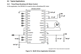
I designed PCB same as the ficture below.

My motor works but stops with nfault problem in a few seconds.

The nfault level drops to low. 

Should I fix the schematic?

What issues should I confirm?

Thanks,

Robert.

  • My motor's maximum current output is 1.6A.

  • Hi Robert,

    Thank you for your question! I have a few questions for you to gain some more clarity on the issue.

    1. Does the nFault pin stay low indefinitely after the fault occurs, or does the nFault pin go back high after some period of time? If the nFault pin stays low until you power off and power on the device or until the nRESET is used to reset the device, then that indicates that the fault is a result of the overcurrent protection circuitry tripping. 

    2. If the nFault pin clears after a certain duration of time, then the fault is either a result of an under voltage event on the VM pin or on a overtemperature event with the device overheating. To determine whether it is a result of an undervoltage fault, on an oscilloscope you can monitor the VM pin while also monitoring the nFault pin to see if it drops below the undervoltage lockout voltage (which is typically 6.3V, but can be up to 8V). An undervoltage event could be occuring if the power supply is unable to supply the necessary current which would cause a dip in the power supply voltage. 

    Regards,

    Anthony 

  • Thank you for your answer Anthony.

    Maybe the problem is current limit.

    I forced nfault to 3.3v high level and the motor works well but it kills the DRV8313 chip.

    I supplied 6 signal steps with no delay below and I think the frequency is too high.

    So, I would like to ask how much current trip level of schematic below and pwm frequency are.

    Regards,

    Robert.

  • Hi Robert, 

    The overcurrent protection trip level for this device is fixed, with a typical level of 5A for the trip level threshold and a minimum trip level of 3A. The amount of current that the motor will consume will depend on the motor that is used, the torque applied to the motor (which is affected by the load), and the speed of the motor. If this current exceeds the overcurrent limit, then the overcurrent protection will trigger and the nFault pin will go low. 

    It looks like what might be happening is that you might be applying a 100% duty cycle to the high side MOSFET during each commutation state (an example is shown below). This will apply all of VM to the motor which can result in a lot of current.

    Instead of applying a 100% duty cycle to the high side PWM, the speed of the motor can be adjusted by applying a lower duty cycle PWM on the high side gate as shown in the image below. This allows the average voltage seen by the motor to be decreased. Adjusting the PWM duty cycle can be used to adjust the speed of the motor. In the image below, a 25% duty cycle PWM is applied to the high side MOSFET, resulting in the average voltage seen by the motor to be 1/4 the VM voltage, which will reduce the current consumption of the motor compared to applying a 100% duty cycle (for a fixed load).

    For the DRV8313, in order to achieve this you can apply a PWM signal with a particular duty cycle to the INx pin that is associated with the output phase that is going to be high for a particular state. As an example, for state 1 (as shown in the image below), Out2 is supposed to have an output high for that phase, so a PWM signal with the desired duty cycle should be applied to the IN2 pin. Adjusting the duty cycle of the PWM that is applied will adjust the amount of average voltage that the motor sees and will adjust the speed of the motor. The duration that the PWM signal is high on the IN2 pin (in the case of state 1) will be approximately the duration that the high side MOSFET of phase V is on, and the duration of time that the PWM signal is low is approximately the duration that the low side MOSFET of phase V is on. This will create an average voltage which will reduce the amount of current consumed by the motor (for a fixed load) compared to when the high side MOSFET is on at a 100% duty cycle (which applies the full VM voltage to the motor)

    Let me know if you have any further questions or clarifications.

    Regards,

    Anthony Lodi

  • Thank you for your answer Anthony.

    Motor works but it has vibration.

    I have another question. How much time duration of ENx?

    I supplied 24KHz PWM to INx as you said.

    Regards,

    Robert.

  • Hi Robert,

    For synchronous rectification (which is achieved by applying a PWM to the INx pin as I described in my previous post), the ENx pin does not need to have PWMs applied, but should be held in the proper state for the entire duration that the motor is in a particular state. For instance, while the motor is in state 1, EN1 should be held low and EN1 and EN2 should be held high for the entire duration that the motor is in state 1. When ENx is logic low, the high side and low side MOSFETs of the corresponding phase are off resulting in the output of that phase being in high-z state. If ENx is logic high, then the INx pin will determine whether the high side MOSFET is on (INx = 1) or the low side MOSFET is on (INx = 0). What method are you using to know when to go to the next state? There are a few methods to achieve this, a few of which are listed below:

    1. Sensored method

          a. Hall sensors on the motor are fed back to the MCU and the MCU uses them to determine where the magnetic field (position) of the rotor magnets are              so that it can apply the appropriate current to the appropriate phases to create a magnetic field on the windings of the motor to move it to the next state.

         b. Encoders or resolvers are other methods for determining the position of the motor which will help know when to change states

    2. Sensorless method

          This method is a more complex, but it uses the back-EMF generated by the motor to determine the orientation of the rotor to know which state to apply to        move the rotor to the next position. 

    Here is a helpful link on describing more about sensored and sensorless methods for motor control. https://training.ti.com/ti-precision-labs-motor-drivers-sensored-vs-sensorless-control. Feel free to check out other videos in the training series. The series is helpful in providing an understanding on BLDC motor driving techniques, methods, and theory. 

    Regards,

    Anthony Lodi

  • Thank you Anthony..

    Your kind answer resolved my problem successfully.

    Regards,

    Robert.

  • Hi Robert,

    Glad I could help!

    Regards,

    Anthony Lodi