Hello Team, following question from my customer:
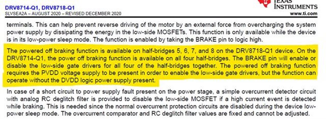
We are currently working on a new system here and had a question about the DRV8718 BRAKE functionality, specifically during overvoltage event (e.g. someone slams the gate, generating voltage on the motors).
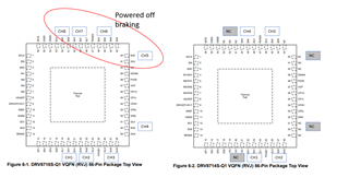
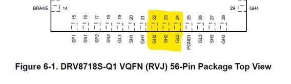
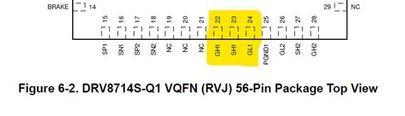
Currently we implemented our main motors with two full H-bridges on channels CH1,2,3,4 on the DRV8718. These motors are the voltage generators during a slam condition. This is especially critical when the battery is disconnected (“power off”) and someone slams the gate. However, after further inspection of the datasheet we have on hand (rev. August 2020), there is a statement that states only CH 5,6,7,8 have this feature on the DRV8718. However, on the DRV8714, the CH 1,2,3,4 have the BRAKE feature (since there is no CH 5,6,7,8). This seems to be a odd design choice. If someone wanted to swap out the DRV8714 w/ DRV8718 and vice versa (same VQFN-56 package), the channels with BRAKE functionality would not align. Based on this, we have some questions listed below.
- Is this datasheet (rev. Aug 2020) correct that only CH 5,6,7,8 on the DRV8718 have the BRAKE functionality?
- Why was it chosen to have opposite channels for BRAKE functionality between DRV8714 and DRV8718?
- If the main motors are moved from CH 1,2,3,4 to CH 5,6,7,8, can the shunt resistor amplifiers (SP1, SN1, SO1, SP2, SN2, SO2) still be used for the main motors?
- i.e. Are the shunt amplifiers independent of which channels they are used on?
- Are the DRV8714 and DRV8718 not swappable?
- i.e. The DRV8714 does not equal less content DRV8718?
- The pinout for each chip in the datasheet we have indicates that there are completely different gate driver channels on each pin.
Many Thanks
Josef