This thread has been locked.

If you have a related question, please click the "Ask a related question" button in the top right corner. The newly created question will be automatically linked to this question.

DRV8701: IDRIVE current calculation

Part Number: DRV8701

Hi Team,

Our customer is using DRV8701 driver in his motor controller project and would like to ask the following questions.

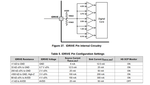
The datasheet mentions the different configuration for the IDrive pin that dictates the gate current. So if the IDrive pin is not connected to anything, I can expect a on/sink current to the gate of 100/200mA. My question is how was that calculated?

Was the threshold voltage of the gate included in the equation when that current was calculated?

Can you also provide the values of the resistors (on/sink) in the driver?

Regards,

Danilo

  • Hi Danilo,

    This is explained in the datasheet. There is an internal pull-up and pull-down resistor on the IDRIVE pin. Then various comparators in the IC compare the IDRIVE pin voltage to various pre-defined thresholds. The Device will then apply the corresponding IDRIVE current.

    In the case of the IDRIVE pin being High-Z, the IDRIVE pin will be equal to AVDD*(310/(310+190)) = 4.8*(0.62)=2.9V. So the first three comparators from the bottom will output a 1.

  • Hi Pablo,

    Thank you for your explanation. I received this additional inquiry of our customer earlier before you replied to this thread.

    Thank you for your response but my question is, how was the 100/200 mA gate current calculated for the specific driver?  I ask this because the basic equation should be I = (Vcc – Vt)/(Rsourse + Rgate) but what value did you use for the Vt (threshold voltage)?  What is the Rsource value?  I ask this question because different transistors will have different threshold values.

    Regards,

    Danilo

  • Hi Danilo,

    I'm confused as to how they came up with the equation. The Idrive currents are chosen by the designers of the chip. The Idrive current will affect the output slew rates according to the equation Qgd/Idrive, where Qgd is the gate to drain capacitance of the FET.

    Please point them to this app-note which describes how our smart gate driver works.