This thread has been locked.

If you have a related question, please click the "Ask a related question" button in the top right corner. The newly created question will be automatically linked to this question.

DRV8308 burning with CSD19536KTT

Part Number: DRV8308
Other Parts Discussed in Thread: CSD19536, CSD18511KTT, CSD19536KCS, CSD19536KTT

Hello,

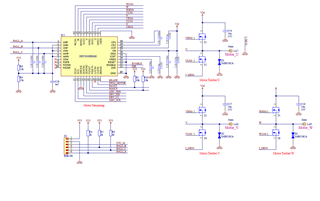
I use an DRV8308 fo drive an BLDC with 18 Volt and approx 100 Ampere. WIth an IRFS7430 the MOSFET was so warm an a low duty of the PWM, taht the MOSFET explode. So I tried an CSD19536, which is much more faster. But with this, the driver DRV8308 burn.

If I use an CSD18511KTT, the MOSFET and driver work good but at 100 Ampere the MOSFET work unexpacted.

What could be the problem, that DRV8308 burn with CSD19536 but not with IRFS7430 or CSD18511?

Regards,

Peter

  • Hi Peter, 

    The CSD19536KCS MOSFET has a leaded package which adds significant inductance to the gate driver and motor current paths. We recommend using surface mount package MOSFETs, not leaded MOSFETs to reduce parasitic inductance and allow for more robust gate switching.

    The IRFS7430 FET has shorter leads and lower parasitic inductance so it can switch 100A current, but you will have higher thermal losses due to higher conduction and switching losses. This is due to the Qgd, Rdson, and rise/fall time of the VDS slew rate. Switching losses are higher in sinusoidal commutation as well. 

    Equations for losses and rise/fall times per FET are below:

    The CSD19536KCS does not burn because the FET can dissipate thermals through the junction-to-air thermal resistance (Theta_JA), so the air is a heat sink and the FET does not burn. But the significant inductance can cause large potential inductive spiking at the power stage due to the added impedance that can couple into the gates, this is called dV/dt coupling. You need to have very small gate drive current, short/wide gate drive paths, and very wide copper pours for the motor current paths to switch 100-A robustly without causing voltage spikes that can damage the DRV8308. 

    Please visit this app note for more information: www.ti.com/.../slvaf66

    Thanks,
    Aaron

  • Hi Aaron,

    thank you for your reply. But we allready try the CSD19536KTT, see post above. With this the driver is damaged. If we use CSD18511KTT, the driver don't have any problem but the maximum current from CSD18511KTT is to low.

    Did you have any other idea why this happen and what we can do?

    We also try to drive the CSD19536KTT with only 10mA but with this low current the MOSFET don't switch. If we go to 50mA, the driver will burn again.

  • Hi Peter, 

    Let me try to get back to you on this tonight.

    Regards,

    Anthony Lodi

  • Hi Anthony,

    this would be great. An additional Information, of I higher TDRIVE from 5 us to 15 us then it seems to work better with the CSD19536KTT. Maybe this information help to figure out the problem.

    Regards,

    Peter

  • Hi Peter,

    You mention:

    We also try to drive the CSD19536KTT with only 10mA but with this low current the MOSFET don't switch. If we go to 50mA, the driver will burn again

    The fact that the driver is damaged while operating using 50mA seems to possibly indicate that there may be significant inductance in the gate path and/or source sense path. during MOSFET switching this can lead to significant ringing if the gate traces have significant inductance. You want to have the gate traces as short as possible, wide (at least 20 mils if possible), and going through as few vias as possible. If you are operating the CSD19536KTT using 50mA gate current, does the driver get destroyed immediately? Does it work with low currents but gets damaged at higher currents? Did you try to use a gate current in between 10mA and 50mA, such as 30mA?

    Layout is really important, especially for high current applications. inductance in high current paths can lead to significant ringing which can possibly damage the driver and/or the MOSFETs.

    Regards,


    Anthony Lodi

  • Hi Anthony,

    the driver was damaged at first cycle with high current.

    After the problem with 50 mA I don’t try more. Only Nö Test with TDRIVE 15us what seems to work better.

  • Hi Anthony,

    another test show, that also with 20mA the MOSFET work and with TDrive of 15us. But if I have a look into my osciloscope, I don't see any change in the switching time with diffrent currents. It is arround 1500 ns, even at 20mA and 130mA?

  • Hi Peter,

    When you are measuring the switch time, are you measuring the source to drain voltage of the MOSFET? This is the correct way to measure the MOSFET switching time. Would you be able to provide a waveform showing that? You will need to use a differential probe unless you are measuring from ground to drain and ground to source of the MOSFETs. If you could also provide a waveform showing the gate to ground voltage during switching that would be helpful to see if there is any ringing on the gate.

    You mentioned that when TDRIVE is increased to 15us then it seemed to work better. Do you mean that you were able to use a gate drive current of 50mA with a 15us TDRIVE setting without damaging the driver? Or do you mean that you were able to get the MOSFET to switch with a 20mA gate current if you increased TDRIVE to 15us?

    Regards,

    Anthony Lodi 

  • Hi Anthony,

    about the last part of your answer. With TDrive set to 5us the driver damage at first high current. Starting from 20mA, if I use TDrive of 15us there is no problem starting from 20mA.

  • Hi Peter,

    Thanks for the clarification, is the issue such that if TDRIVE is set to 5us and 20mA gate current is used that results in the MOSFET not being able to switch, but if TDRIVE is adjusted to 15us then the MOSFET is then able to switch without any  issues? If so, this could be because using 20mA of gate current is not able to switch the MOSFET fully on fast enough since the gate drive current is applied for 5us instead of 15us. When you use a TDRIVE of 15us that will allow the gate current to be applied longer, allowing the MOSFET to switch on fully.

     Another aspect of TDRIVE is that it applies an active pulldown current on the MOSFET that is supposed to be off to reduce the chances of switching noise from one MOSFET coupling into the gate of the other MOSFET that is not switching. The duration of time that the pulldown current is applied to the MOSFET that is not supposed to be switching is TDRIVE, so having a higher TDRIVE will result in this active pulldown of the gate of the MOSFET that is off being applied for a longer duration of time, which will help if there is a lot of switching noise that could couple into the gate of the MOSFET that is supposed to be off.

    Once you provide the waveforms mentioned in my previous post I will take a look at them and see if that can give some direction on the cause of the issue. 

    I noticed that you don't have any current sensing that I could see in the schematic you provided. How are you ensuring the appropriate amount of current is supplied to your motor? 

    Regards,

    Anthony Lodi

  • Hi Anthony,

    it seems to be good with this Seetings.I have forgot the scope pictures but from drain to source the switching is in the expect range!

    Probleme we now have is, that some replaced Mosfet burn. I not sure if this is an Mosfet problem or solder problem. One of them burn after the first cycle with 100Amps run nice, but as try to Start second cycle the Mosfet explode before any current Flow.

  • Hi Peter,

    Glad to hear that the switching is in the expected range! Do you have a thermal reader available? I would strongly suggest taking a thermal reading at the peak current to see if the MOSFETs are getting really hot which may lead to damage that is observed next time you start the motor. Also, what method do you use to brake the motor? During braking you need to safely bring the motor to a stop, and you have to be careful in this because there is a lot of current and back-emf that needs to be dissipated. If you are turning on the low side MOSFETs and recirculating current through the low side MOSFETs, you need to make sure that the MOSFETs can handle the high current that will be generated by this method of braking.

    Regards,

    Anthony Lodi

  • Hi Anthony,

    thnak you again for you reply. We got today our new parts and we soldered them carefully to our PCB. It seems to work very well now, also with an TDrive of only 1us. So we will continue with stress test and I hope that we have our solution.

    Thank you again for your great and fast help.

    Regards,

    Peter

  • Hi Peter,

    Glad to hear about the progress! Let us know if you have any further questions.

    Regards,

    Anthony Lodi