This thread has been locked.

If you have a related question, please click the "Ask a related question" button in the top right corner. The newly created question will be automatically linked to this question.

DRV8244-Q1: DRV8244-Q1 Inquiry about noise generation during circuit configuration

Part Number: DRV8244-Q1
Other Parts Discussed in Thread: DRV8244S-Q1LEVM, DRV8243-Q1

Hi, TI expert.

The customer referred to the EVM board (DRV8244S-Q1LEVM) and applied DRV8244-Q1 (DRV8244SQRYJRQ1) to configure the controller to control the seat of the electric car's leg.

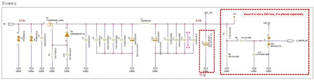
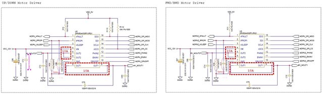
The circuit below is the power part and motor driver circuit among the controller circuits.

The reason for using two motor drivers is that one driver is required for each of the front/rear and up/down control in the leg seat, so it is configured like this.

A strange sound occurs during circuit configuration and testing, and we ask a question to determine the cause of the noise.

Symptoms include:

① Section: Current magnitude in the section where the folding switch is continuously pressed while the seat is folded
② Section: Current magnitude in the section where the switch is first pressed to move the seat up
③ Section: Current magnitude when the seat is moved to the uppermost position
④ Section: Current magnitude in the section where the switch is first pressed to move the seat down

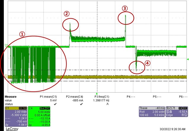
If you look at the current waveform in the 4 sections above, you can see that the current is more than 10A, and a “tick tick” sound occurs in this section. (Check the attached video_'noise generation video')

The customer expects the noise (shattering sound) generated by L (inductor) in the CLC circuit configuration of the power part.

The L (inductor) used in the circuit is 7443320100 (Wurth Elektronik), and the same inductor used in TI's EVM board (DRV8244S-Q1LEVM) was used.

Q1) Is this noise caused by the inductor as expected by the customer?

Q2) Or is there another cause?

Q3) Is there a solution depending on the cause of the noise? Could you please let me know if you have a guide?

Please check.  Thank you.

  • Hi Grady,

    Thank you for sharing your customer's question. Not sure where tick tick sound comes from. My understanding is coil could make sound/noise by audible frequency switching regulator etc, but not like this tick tick noise.

    However we have way to reduce peak current. DRV8243-Q1 has ITRIP current regulation function. By adjusting ITRIP level, DRV can reduce peak current from 10+A. 


    regards

    Shinya Morita

  • Hi, Shinya Morita

    I think it's a good idea for you to limit the current to 10A or less using the ITRIP level, but it's a little lacking to solve the fundamental problem.

    As a result of the test again, it was confirmed that the tick-tick sound is generated by the inductor (L1), and the configuration of C9, L1, and C10 in the circuit is known as a pi filter.
    This filter is used for the purpose of attenuating noise in signals and power lines. I would like to know if the filter design needs to be changed to remove the currently generated sound.
    If you need to change the filter design, I want to know how to change the spec. of capacitors and inductors.
    Please check my comments and don't hesitate to let me know if you have any questions.
    Thank you.

    regards

    Nam

  • Hi,

    Thank you for sharing update. We do not have such a experience of mechanical noise on TI EVM, I was wondering what is the root cause. Good to know you find the root cause. May be Inductor heat up then generate mechanical noise on your board?

    Maybe the you could try testing the circuit with increasing/decreasing current loads by using different resistive loads, and see if the noise is related to the load current level.

    The filter on EVM is just example as reference design and it is not a part of our DRV device condition. Each customer design/adjust the filter based on their PCB, application to meet customer's EMC requirement. So changing filter value/component from EVM design is not problem at all. 

    In general with the pi filter, try to have as much L and  C as possible, with the tradeoff being the size and cost of the L and C components.  It becomes difficult to get a large inductance value in a reasonable size if there is a lot of current through it.

    Here is TI application note as reference, sections 4.1 and 4.2:

    EMI and Thermal Design Tips and Tricks for 48-V IGBT/SiC/GaN Automotive Supply

    regards

    Shinya Morita