Other Parts Discussed in Thread: DRV832X
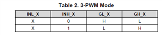
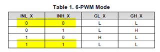
I am using a DRV8302 to drive a BLDC motor. I would like to run it in sensor less mode. I have configured the PWM mode as 3 PWM.
I am feeding 3 timer outputs from MCU to the DRV8302 three input pins, INH_A, INH_B, INH_C.
INL_A, INL_B, INL_C are connected to ground (since mode of DRV8302 is 3 PWM)
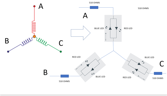
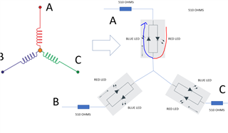
The idea here is:- to sense backemf, ie when one channel is driven high, second channel driven low and the third channel is not driven and is fed to amplifier to sense voltage.
So channel A is driven high, channel B is driven low and channel C is used for Back EMF measurement.
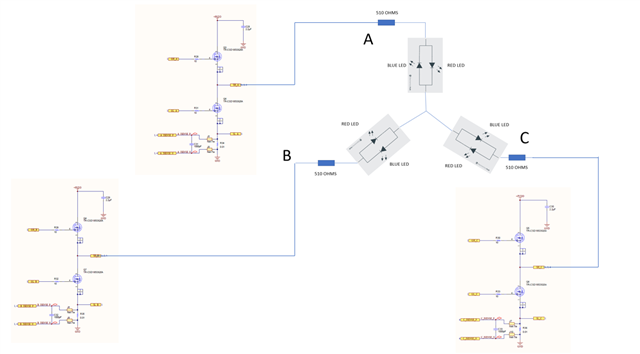
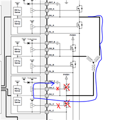
ie when INH_A is held high, INH_B is held low and INH_C is held in high impedance state, Top push pull MOSFET (pair1) shall be turned ON by Gate A, bottom push pull MOSFET (pair2) shall be turned ON by Gate B and no push pull MOSFET (pair3) shall be turned ON by Gate C. That is current flows through the Winding A of Motor, and goes out through winding B of the motor and Winding C is used to measure the Back EMF.
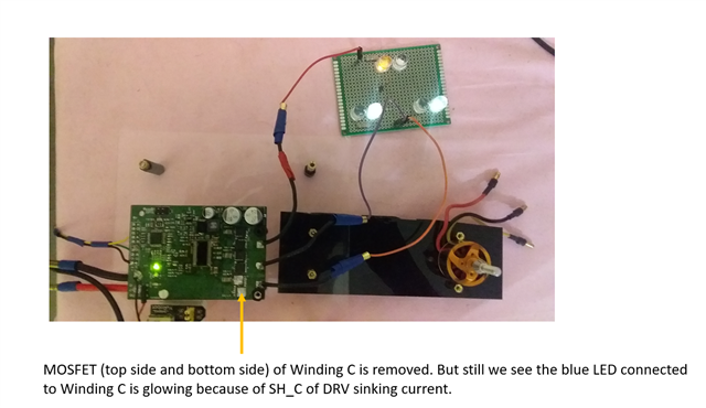
But I am not able to do this. When I drive channel A high, I see current flows through winding B and Winding C. That is because the bottom push pull MOSFET ( of pair2 & pair 3) are turned on by Gate B and Gate C for the current to flow down to the ground.
How can I sense backemf using DRV8302 if this is the operating mechanism?.
Please share your thoughts on this to help me.
Thanks & Regards
Anand