This thread has been locked.

If you have a related question, please click the "Ask a related question" button in the top right corner. The newly created question will be automatically linked to this question.

DRV3245E-Q1: If there any standard for checking BLDC current waveform by FOC

Part Number: DRV3245E-Q1

Hello expert friends,

Our SW friend tried to use FOC to drive one motor by DRV3245E-Q1 with 3 shunts, it worked but we don't know whether it is standard FOC result. If there any standard for checking BLDC current waveform by FOC, who can help to provide some suggetions or materials?

Thanks in advanced.

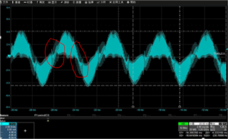
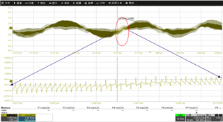
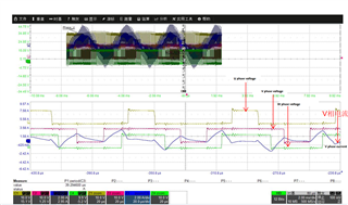
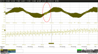
Fig. 1 Motor light load test results 

  • Hi Hongda,

    The FOC looks okay but there is probably vibration or ripple occurring still in the motor from the look of the waveform. We are not FOC software experts so we can't comment from the control side much, but here are a few considerations to improve the FOC waveform:

    1) Can you use 3x PWM mode, or can you ensure that in 6x PWM the inputs are synchronous with minimal dead time at the MCU inputs? Any asynchronous rectification can mess up the integrity of the FOC output currents. 

    2) Can you use smaller IDRIVE settings to see if gate switching improves and overshoot/undershoot does not occur at the phase voltages?

    3) If using sensorless-FOC, can you ensure the correct phase and current feedback voltages are read through the MCU's ADC? Is there calibration done or a way to ensure that the board removes offsets from the measurement? Is the motor inductance and resistance correct?

    Thanks,
    Aaron 

  • Hi Aaron,

    Thanks a lot for your support, please check my reply for your questions:

    1) MCU outputs 6 PWM, but INHx would be complementary to INLx, there is dead time between INHx and INLx.

    2) IDRIVE should be 250mA

    3) Sensors are used in this project. So phase voltage is not used.  Current are read through the MCU's ADC, and the offsets are removed by 0A calibration.  The motor is real motor not dummy load, so I think the resistance and inductance should be OK.

    BTW, the picture is phase current behavior, do you have any phase current waveform by FOC on your side?

    Thanks,

    Hongda

  • Hi Hongda, 

    Thanks for the additional info - will check w/ the team to get an updated response to your latest questions/requests

    Best Regards, 
    Andrew 

  • Hi Hongda, 

    Thanks for the patience on this - I did get a chance to discuss further with the team. 

    For some general comments about FOC performance: 

    • we generally look at the phase current and voltage waveforms, and consider ripples to be signs of non-ideal commutation 
      • this ripple in V/I waveforms can translate into torque ripple
      • and also acoustic noise if the ripple is within audible frequency spectrum 

    Some questions and comments about your situation: 

    • Question: when you say that the project is using sensors with current feedback, are you referring to Current Shunt Amplifiers? 
      • and if so, are you using the CSAs integrated in the DRV3245 device? 
    • A few suggestions from my team members: 
      • the phase current waveform you shared does appear to have some ripples
      • this could be due to motor having very low inductance and lower-end switching frequency for output PWM 
      • one way to improve the waveform could be to improve current sensing accuracy (by setting lower CSA gain and/or choosing higher Rshunt resistor values

    As for some resources on FOC, I found the below links for your reference:

    Thanks and Best Regards, 
    Andrew 

  • Hello Andrew,

    Thanks a lot for your support and sorry to let you and your team confused.

    We have used HALL sensors. And the CSAs integrated in the DRV3245 device are also used.

    Your suggestions are very helpful, our PWM setting is 15kHz and CSA Gain is 40V/V, and the shunt is 0.5mΩ. Maybe we need to consider changing the settings.

    And I check the fomula below based on DRV3245, Vref=5V, k=2, G=4(tolerance is +/-1%), Rshunt=0.5mΩ(tolerance is +/-1%). If we just decrease Gain without changing the tolerance and increase Rshunt without changing the tolerance, let me assume that G=2(tolerance is +/-1%), Rshunt=1mΩ(tolerance is +/-1%), the multiplication result is same, but the final tolerance also seems same.

    So could you please help to provide some explaination or some hints why this changing can improve current sensing accuracy so that I can persuade team to change these settings. It is also OK if you can provide some material for current sesing accuracy calculation basded on DRV3245.

    Thanks and Best Regards, 

    Hongda

  • Hi Hongda, 

    Thanks for the follow-up, and I have some updated comments below: 

    1. So in your CSA input vs output equation, the intention of my earlier statement is to suggest that your team use as much of the CSA output voltage range** as possible when doing voltage-based feedback on the motor phase current 
      1. In your example, 
        1. VREF=5V, k=2, G=40V/V, Rshunt=0.5mOhm, and motor phase current is about +/- 4A according to the waveform 
        2. so in this scenario, VO= 5/2 - 40*(4*0.0005), which equates to VO = 2.5V +/- 0.08V
        3. so your MCU's ADC is trying to sense very small variations in the CSA output, on the order of tens of mV 
      2. Instead, if you were to increase CSA range and still expect +/- 4A phase current, 
        1. VREF=5V, k=2,G=40V/V, Rshunt=6.25mOhm
        2. the new scenario will have: VO=5/2 - 40*(4*0.00625), which equates to VO = 2.5V +/- 1V
        3. now your CSA output voltage swing is a whole +/- 1V that is easier for the MCU ADC to measure, and less sensitive to noise/error 
      3. in using more of the CSA range, it becomes easier to detect the motor current (and position) more accurately, since it does not place as much burden on the precision and sampling rate of the MCU ADC 

    2. Also on the topic of PWM switching frequency and motor inductance, 
      1. my colleague's advice on this is that if your motor has very low inductance (on the order of 10-50 micro Henry for example),
      2. then low PWM frequency on order of 20-30kHz may result in noticeable current ripple 
      3. this resource I found online may be helpful to explain further:
        1. https://www.celeramotion.com/applimotion/support/technical-papers/achieving-optimal-motion-system-performance-with-low-inductance-motors/#:~:text=Low%20inductance%20motors%20may%20require,suited%20for%20low%20inductance%20motors.

    I think both considerations above may help in your system design, but the current ripple might just be more-so due to the low inductance of the motor (if on scale of microHenry instead of milliHenry)

    Thanks and Best Regards, 
    Andrew 

  • Hello Andrew,

    Sorry for my late reply. We would consider your sugestions, thank you very much~

    We also look at the phase current and voltage waveforms,the measurement voltage waveforms should be standard six sector waveforms. The current ripples should be cuased by 6-MOSFET changing during 0A crossing area.

    Maybe I can find the reason for this behavior according to Kirchhoff laws, is it correct or do you have any other suggestion?

    Fig. 2.1  Current waveform with Zoom in

    Fig. 2.2  Current and voltage waveform with Zoom in

    Thanks and Best Regards, 

    Hongda

  • Hi Hongda, 

    Thanks for the updated response and detailed waveforms!

    From the latest alignment I had with my colleagues, I think our working theory is still that this current ripple behavior is likely due to natural performance of a very low-inductance motor, and the combination with insufficient PWM frequency.

    • Would you be able to share the info about your motor's specifications? 
    • what PWM frequency are you using? Just want to confirm this # with you directly, rather than guessing based on the waveform images
      • can you try increasing the PWM frequency in your commutation code, to see if it reduces the ripples a noticeably? 

    The basis for the above reason is detailed further in the article link I shared. 

    • But essentially, the relationship is V=L*di/dt
    • If your system is switching known voltage with a motor of known inductance, then the rise time of current is related to the amount of time during that voltage differential.
    • Therefore, if your PWM freq is too slow - then your PWM period is consequently too long -> resulting in significant current rise/fall (a.k.a. ripple) at every PWM switching interval
    • This means you can reduce the time period in that equation by increasing PWM frequency, and see smaller current rise/fall. 

    Best Regards, 
    Andrew

  • Hello Andrew,

    I'm sorry that I should have give you the motor parameters.

    It is real motor, the inductance is 52uH(L1=L2=L3=52uH), the resistance is 60.9mΩ(RL1=RL2=RL3=60.9mΩ).

    The PWM frequency is about 15kHz, sorry again that we couldn't verify that if it is better after increasing the PWM frequency because we work at home therse days for the reason of COVID-19, I will try to verify it when we can go to office and give you a feedback as soon as possible.

    Fig. 3 Triangle connection type

    Thanks and Best Regards, 

    Hongda

  • Hi Hongda, 

    No worries on the schedule - we are here to support as needed.

    From looking at the motor inductance value being in the microHenry range and PWM being 15kHz,

    • I believe the current ripple you are seeing is expected in this situation

    Thanks for discussing through this issue with us, and we hope that increasing the PWM frequency resolves your problem! 

    Feel free to follow up in this thread w/ the results once available, or if additional assistance is needed.

    • Also, regarding freq increase, the magnitude of the change might have to be quite significant to reduce the ripple (e.g. 2x, 3x) 
    • although even smaller increases gradually might have a noticeable effect on reducing current ripple

    Best Regards, 
    Andrew 

  • Hello Andrew,

    Good news that one colleague in office helped us to perform two groups of test,  wihch are 20kHz PWM frequency(see Fig. 4.1) and 30kHz PWM frequency(see Fig. 4.2).

    Obviously, the ripple is decreased as the PWM frequency is increased.

    But the current waveform behavior seems almost same when compared current waveform of zoom in part for different PWM frequency result. I would try to figure out the reason of zoom in part behavior based V=L*di/dt you mentioned and the article you proposed.

    Thank you and thanks to TI team for your support and Best Regards

    Hongda

    Fig. 4.1  Current waveform with Zoom in(20kHz PWM frequency)

    Fig. 4.2  Current waveform with Zoom in(30kHz PWM frequency)