This thread has been locked.

If you have a related question, please click the "Ask a related question" button in the top right corner. The newly created question will be automatically linked to this question.

DRV8316REVM: DRV8316REVM GUI Problems

Part Number: DRV8316REVM
Other Parts Discussed in Thread: MCF8316A

Hello,

I was going to validate the DRV8316REVM using the GUI but I am running into a few issues.

Using the InstaSPIN GUI seems to always overdrive the motor that I am using and it ended up shorting one of the motors today. Motor Identification looks like it works but the moment I try to drive the motor after that, the motor starts to jitter and draw a lot of current.

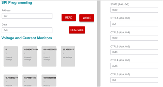
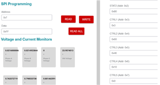
On the other hand, I tried using the Sensored Trapezoidal GUI and it worked flawlessly with the same motor at much lower currents. The only problem is that I can't seem to write to the SPI registers with this GUI.

I can always just write my own code, but if this can be fixed this way would be a lot easer. Let me know if I am doing anything wrong.

Jerome

  • Hi Jerome,

    For the DRV8316REVM InstaSPIN GUI, could you start with spinning the motor at a low electrical speed, i.e. 10 Hz? I have noticed that the acceleration in this is actually fixed and has a pretty poorly tuned speed and torque loop, meaning if you start spinning the motor at too fast an electrical speed, the speed loop will overshoot and oscillate until it settles at the right speed. This results in a huge overshoot in supply current and could be why one of the motor phases is shorting. 

    If the motor jitters during identification, then it may not be identifying the motor parameters correctly. I have found that if the motor phases are not connected correctly, the identification current will be much larger and this will cause problems in motor identification and running.

    For the sensored trapezoidal GUI, I will need to double check it today as the wrong version of the GUI may have been uploaded to the Gallery. 

    Thanks,
    Aaron

  • Hi Aaron,

    I guess the question is, how do you know if identification worked well? Yesterday, I did motor identification multiple times on the same motor (with indeterminate breaks in between) and I feel like it always arrived at different values. Sometimes it would work well (spin smoothly), sometimes not so smoothly (cogging/jittering). Is this the best way to evaluate if identification succeeded?

    Sensored trapezoidal is more in line with what we want to do so it would be nice if we can evaluate all the features of this motor driver with this type of control.

    Thanks,

    Jerome

  • Hi Jerome, 

    InstaSPIN-FOC is a C2000 owned algorithm, and I know typically it has some variability with low-inductance motors and there is differences in Rds(on) variation internally when spinning the motor at higher peak currents. This works well with low-power motors (<25W) but there is some uncertainty with higher power motors (25-70W), where we recommend MCF8316A for evaluation over this FOC solution. 

    For sensored trapezoidal, I found a couple of bugs in the GUI that I will fix by tomorrow with SPI. I'll let you know once I update the GUI tomorrow!

    Thanks,
    Aaron

  • Hi Jerome,

    I fixed the sensored trap GUI and it works with SPI now: https://dev.ti.com/gallery/view/BLDC/DRV8316REVM_Sensored_Trapezoidal_GUI/ver/1.0.0/

    Thanks,
    Aaron

  • Sweet! Will test it momentarily.

  • So I am kind of confused about how the SPI should work:

    I am trying to write 0x6 to register 0x7 (CTRL5) like so by typing 0x7 in Address and 0x6 in data then pressing the WRITE button:

    Nothing updates so I press the READ button and I get 0xFF in the Data field:

  • So it seems that double-clicking the write button and then pressing read all updates the registers on the right.

  • Hi Jerome, 

    I apologize I did not describe much about how the GUI works because this GUI is new and has not been documented in the User's Guide. 

    For SPI to work, the following steps should occur:

    • After the supply is powered on and the GUI loads, it should automatically 
      • Unlock the SPI registers by writing 0x03 to register 0x03
      • Read all defaults in the registers
    • To write SPI:
      • Enter the address in the Address box in hexadecimal, press Enter
      • Enter the data in the Data box in hexadecimal, press Enter
      • Press the WRITE button
    • To read SPI:
      • Enter the address in the Address box in hexadecimal, press Enter
      • Press the READ button
      • The data should appear in the Data box in hexadecimal
    • To read all registers:
      • Press the READ ALL button
      • All registers should be updated on the SPI registers on the right

    Thanks,
    Aaron

  • Another question, does the GUI work with the different PWM control modes? i.e. 3x PWM/with current limit.

  • The GUI does not work in 3x PWM, only 6x PWM mode. I have code for 3x mode to work, would you be open to using a simple code in CCS to test the 3x mode? 

    Thanks,

    Aaron

  • I messaged you the 3x code.