This thread has been locked.

If you have a related question, please click the "Ask a related question" button in the top right corner. The newly created question will be automatically linked to this question.

DRV8316: Hall filtering

Part Number: DRV8316
Other Parts Discussed in Thread: MCT8316Z, ,

Hello, we are using the DRV8316 and MCT8316Z in our system and had the following questions

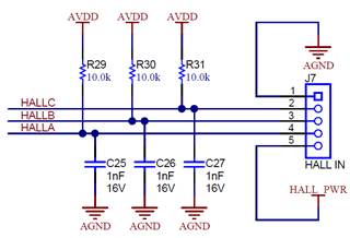
For the DRV8316, hall signals are coming from the motor to the microcontroller. We are thinking of adding a pull-up and a TVS diode. Would you also recommend adding a series resistor and small capacitor to improve filtering?

For the MCT8316Z, is any filtering needed on the halls at all? Also, what is the max IO voltage of the halls? Is 5V okay? The datasheet seems to be missing this information.

  • To clarify, we will be using digital halls for the MCT8316Z

  • Hi Daniel,

    Typically we implement Hall pullups and small filtering capacitors as follows for digital hall outputs. We do this on the DRV8316REVM as shown below. 

    DRV8316REVM:

    A small series resistor and cap can further help filtering but it not required. Same as the TVS diode, it can help with any transients but is not required. It depends on whether you think the Hall signals will be susceptible to noise in your system. 

    For the MCT8316Z, the Hall inputs should not exceed AVDD. Therefore 5V is too high and should not be used. Filtering can be used but is not required in digital hall signals as long as there is a pullup to AVDD or lower. 

    Thanks,
    Aaron

  • Is it recommended to use the AVDD power or on-die buck converter to supply power to the halls on the MCT8316Z?
    What happens if a 5V hall signal goes to the hall inputs on the MCT8316Z?

  • Hi Daniel, 

    Since an ESD diode rated for AVDD protects the hall inputs HPx/HNx, it is not recommended to use a 5V hall supply signal. I will need to check with design what the "snapback" voltage of the ESD diodes are here. This voltage means when it is exceeded, the ESD diode fails, the I-V curve snaps back to a lower voltage, and a significant amount of current can flow into AVDD through the shorted ESD diode. 

    It depends on how much supply current is needed to power the Hall sensors. The buck can supply up to 200-mA (depending on the filter used) and AVDD can supply up to 30-mA. 

    Thanks,
    Aaron

  • Do you mean 30 mA for the LDO? What is the failure mode if you draw too much current?

  • Additionally,, can you confirm whether the following are okay:
    - Leaving HNX pins floating when digital halls are used
    - Keeping FG and nFAULT pulled up to 3V3 even when driver is asleep
    - Not using brake pin (pulled to GND) and changing brake status over SPI

  • My apologies, I meant to say 30mA. I corrected in the previous reply. If you draw too much AVDD current, then AVDD will start to brown out and drop in voltage. If VAVDD goes below VAVDD_UV, then an AVDD_UV fault will occur. 

    1) You can leave HNx pins floating as long as you are in Digital hall input mode (see PWM_MODE below)

    2) Yes you can pull up FGOUT and NFAULT to 3.3V. When the driver is asleep, the logic core is shut down and everything is disabled except the nSLEEP pin, and the device only draws 1.5uA. nFAULT and FGOUT will not draw any current as the internal MOSFETs for the open-drain configuration are off. 

    3) Absolutely, you can use BRAKE bit over SPI instead of the BRAKE pin (disabled by tying to GND). The BRAKE pin and BRAKE bit are OR'ed in the device. 

    Thanks,
    Aaron