Hi Experts,
Good day. Seeking your assistance on this query:
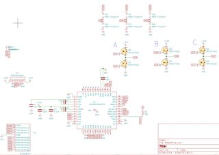
I made a motor driver with the schematic below. When I write 100% power to the power pin, the motor is powered at a high speed (Im assuming 100% power), so that is no problem.
The issue is that I can not control the low speeds of the motor. When I write 10% PWM to the driver after I have the motor already spinning, the motor completely stops instead of going slowly (I even tried spinning it by hand to help it start if that was the issue but to no avail).
When I write anything below 40% after the motor stops spinning, the motor will still not turn on (again, even when I start spinning it by hand to help it).
In summary, I cannot make the motor go below 40% power from a standstill (when I try to do so the motor just stops), and I cannot make the motor slow down to under 10% power from an already spinning state (the motor stops spinning below 10% pwm duty cycle even if it was spinning already).
Tried fix:
I thought the PWM write frequency to the driver was messing it up so I scanned every frequency from 100,000 to 0 in increments of 1000 and found that 19,000 was the frequency with the lowest PWM that was able to turn the motor when going from already spinning (around 10% power/PWM duty cycle). The other frequencies did not turn the motor at all, or alternated between turning the motor and not turning the motor.
I made 4 of these motor drivers and put them in parallel, receiving the same power and signal. At 19,000hz PWM, I decreased the power from 100% to 0% over one minute and found that some of the motors/drivers stopped about +-2% power from each other. In other words, there was a period of duty cycles where some of the motor drivers kept turning at the desired speed while others completely stopped. Im not sure if this has anything to do with the stopping at low input duty cycle issue, and may be just manufacturing/assembly error.
I know that brushless motors and brushless motor drivers, in general, are able to be operated at slow speeds. Is this a chip limitation or is there a fix?
Could I have mixed up the hall sensor pins or motor pins to be out of order?
Regards,
Archie A.