This thread has been locked.

If you have a related question, please click the "Ask a related question" button in the top right corner. The newly created question will be automatically linked to this question.

MCT8316Z: Schematic review

Part Number: MCT8316Z

Hi,

The customer constructed a schematic diagram referring to Figure 9-1.

However, the motor is not working.

Please review the schematic.

MCT8316_schematic.pdf

FGOUT is MCU and Disconnection status.

Do not use MCT8316ZT built-in BUCK.

Operation test according to the presence or absence of built-in LDO AVDD: It does not work.

The Hall Sensor voltage is applied with an external 5 volt voltage.

DR & BRAKE PORT uses MCU GPIO Port and does not use PWM Control Mode.

  • Hi Cho,

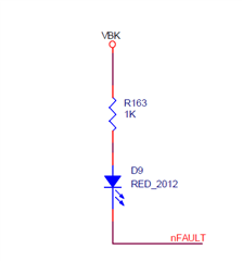
    nFAULT is pulled up to VBK and VBK is not used. Therefore nFAULT is low and driver will not be operational. Please pull up nFAULT to external 3.3V or 5V pullup. 

    Thanks,
    Aaron

  • Hi Aaron,

    The nFAULT connection test with external 3.3V instead of VBK shows no change in behavior.

    Please check if there are any other problems.

    If there is anything needed for analysis, I will ask the customer.

    Thank you for your support.

  • Hi Cho,

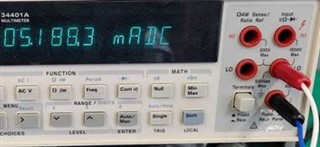
    Can you confirm nSLEEP = 1 and DRVOFF = 0? Does customer see ~10mA of nominal current for the MCT8316Z when it is in idle mode vs sleep mode? 

    Has the customer spun the motor yet with this device or has not gotten it to work yet?

    Thanks,
    Aaron

  • Hi 

    nSLEEP = High, DRVOFF = Low fixed.

    nominal current : 5.18mA

    The motor does not operate at all, not even a "tick" sound.

  • Hi Cho,

    Today is a holiday in the US, I will get back to you tomorrow.

    Thanks,
    Aaron

  • Hi Cho, 

    Apologize I did not get back to this. Can you share layout?

    Thanks,
    Aaron

  • Hi Aaron,

    I asked the customer for a layout. Please wait.

  • Hi Cho,

    I have some more ideas while we await layout:

    1) Can we check the powerup sequence of the MCU vs VM? 
    2) If the VM powerup is strange, can the ferrite bead be removed and shorted?
    3) Can you check the soldering of the AVDD pin on the package? The best way to tell if the soldering is bad is measuring the continuity from the AVDD bypass cap to the AVDD pin, it should be a short. 

    4) Is this occurring on multiple boards or just 1 board?

    5) When powering the MCT8316Z, can you monitor on an oscilloscope:

    - VCP (should be 5V above VM)
    - VM
    - nFAULT (should be at 3.3V before VM goes above VM_UVLO)
    - VBK (should be 3.3V at powerup)

    Thanks,
    Aaron

  • Hi Aaron,

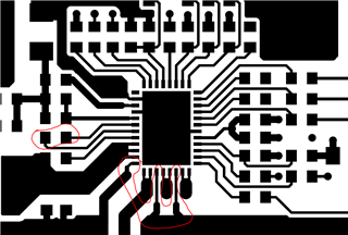
    I attached the layout file.

    Request is being checked.

    gbr.pdf

  • Hi Cho,

    I don't have many concerns with the layout. Only two comments I have are:

    1) CPH-CPL cap is a little far, check if VCP = VM+5V to ensure charge pump is working sufficiently
    2) PGND traces have some thin inductance/impedance for motor current path, make sure that motor current for each phase can travel through the thin trace and back to the PGND ground plane and back to the supply. Check if impedance/inductance is added from the PGND pin at the device to the negative of the supply. 

    In regards to AVDD, can you check the impedance of AVDD-GND with respect to a known good MCT8316Z0T device? Maybe AVDD exceeded the 30-mA limit and damaged from there being two 0-ohm resistors for the hardware resistors (VSEL_BK, ADVANCE, MODE, SLEW). 

    Thanks,
    Aaron

  • Hi Aaron,

    Update the customer's answers.

    Please give me some advice to solve the problem.

    1) Can we check the powerup sequence of the MCU vs VM? 

    -> VM will power on first.

    2) If the VM powerup is strange, can the ferrite bead be removed and shorted?

    -> VM output appears to be fine.

    3) Can you check the soldering of the AVDD pin on the package? The best way to tell if the soldering is bad is measuring the continuity from the AVDD bypass cap to the AVDD pin, it should be a short. 

    -> AVD pin solder is fine.

    4) Is this occurring on multiple boards or just 1 board?

    -> Just 1 board

    5) When powering the MCT8316Z, can you monitor on an oscilloscope:

    - VCP (should be 5V above VM)
    - VM
    - nFAULT (should be at 3.3V before VM goes above VM_UVLO)
    - VBK (should be 3.3V at powerup)

    -> Both VCP and VM are output at 19V.

    nFAULT is coming in late.

    nFAULT does not reach 3.3 V before the VM reaches VM_UVLO.

    VBK 6V output.

  • Hi Cho,

    -> Both VCP and VM are output at 19V.

    nFAULT is coming in late.

    nFAULT does not reach 3.3 V before the VM reaches VM_UVLO.

    VBK 6V output.

    These comments seem that the MCT8316Z0T device is damaged. I am not sure what has caused the damage yet. Can you check the impedance of each pin to GND and compare with a known good device to see if any pins are shorted or open?

    Can you replace the device with a new one to see if these rails when the device powers on is normal?

    If the rails do not power up normally after replacing the device with a new one, then we can do further debug on the PCB.

    Thanks,
    Aaron

  • Hi Aaron,

    The customer is going to SWAP test when the MCT8316Z sample arrives.

    I will reply to you later after the case is closed.