Part Number: DRV8432
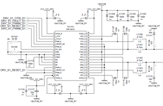
We are using DRV8432 in PFB mode to drive a brushed DC motor. The circuit schematic is given in "drv8432_cct.png". The PVDD voltage is 28V, and the switching frequency is 100kHz. We are using closed loop current control to drive the motor. During operation at around 10A, the driver time to time supplies approximately 0V to the motor as can be seen in the "Voltage_Current.jpg" oscilloscope screenshot in which the yellow line shows the current waveform and the blue line shows the voltage waveform between the motor terminals. Normally, I expect the driver to switch the voltage between +28V and -28V since we are using it in PFB mode. And since the current is lower than the current limit, I don't think that the driver is entering cycle-by-cycle current limit protection. Even if it does enter the cycle-by-cycle current limit protection, it shouldn't be supplying approximately 0V to the motor since in the datasheet it says during cycle-by-cycle current limit protection the half bridge is being set in Hi-Z state.
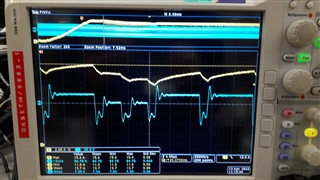
I also probed and observed the VREG voltage of the driver referenced to the AGND pin. As can be seen from "VREG_Oscillations.jpg" oscilloscope screenshot, the VREG voltage also oscillates during the 0V cases. In the screenshot, the yellow waveform represents the current, the blue waveform represents the voltage between the motor terminals and the green waveform represents the VREG voltage of the driver referenced to the AGND pin. I also observed the PWM waveforms on the PWM_A & PWM_B pins of the driver. These waveforms also seem to be affected similar to the VREG voltage during the 0V cases.
Then I changed the 100nF capacitor between the VREG and AGND pins with 1uF capacitor. This change more or less solved the oscillation issue on the VREG voltage but the 0V case still continues.