This thread has been locked.

If you have a related question, please click the "Ask a related question" button in the top right corner. The newly created question will be automatically linked to this question.

DRV8305-Q1EVM: How to capture a full sine wawe without offset with ADC

Part Number: DRV8305-Q1EVM

Im working on a motor spin project using DRV8305-Q1EVM .

My main problem is that i cannot get any negative results while reading a "sine" wave from ADC.

EVM board has no sensor or OPAMP circuit on sampling side of system.

But the projects that prepared by TI , has no such issue. On the same hardware ,TI projects managed to capture a full sine wawe.

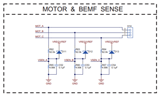
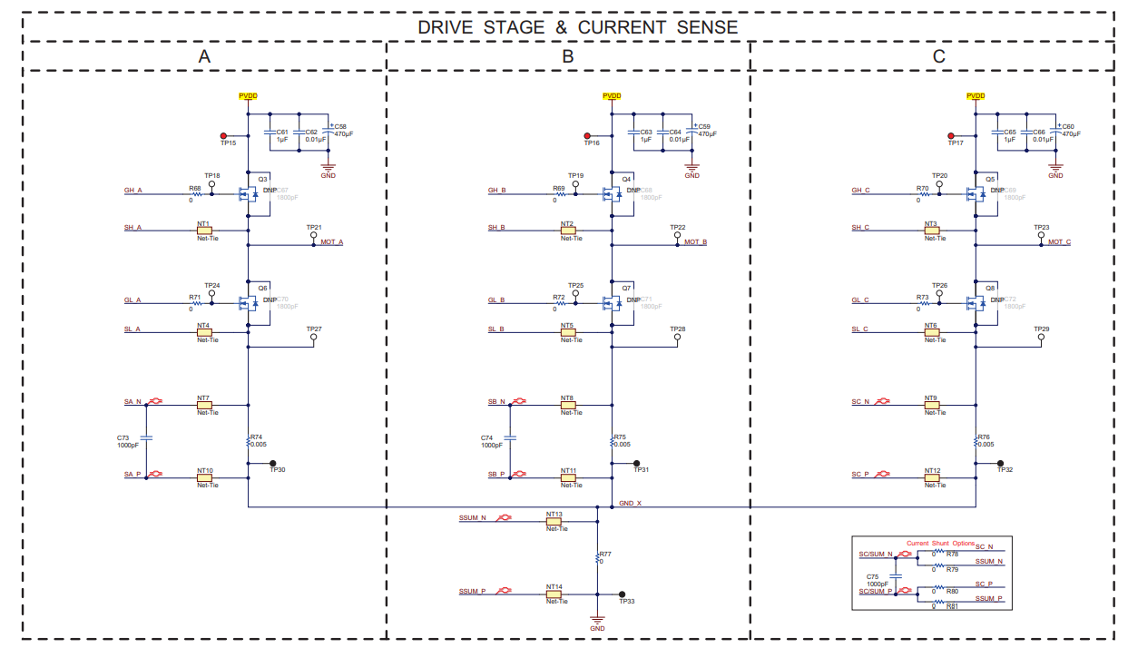
These are the voltage and sense circuit on EVM . The last picture is my desired and current adc reading.

What should ı do in order to capture a full sine wave from ADC . 

Thank you,

Efe

  • Hi Efe,

    Thanks for your question!

    The DRV8305EVM uses a single shunt resistor, where the sources of the low side MOSFETs are tied together and connected to a single sense resistor to ground. This means that the current flowing through the sense resistor is the sum of all the current flowing through all of the phases. As a result, the voltage drop across the single sense resistor will always show positive current. In order for the ADC to capture the negative and positive currents flowing through each individual phase you would need to have an individual sense resistor and CSA for each half bridge, instead of 1 sense resistor that measures the total current through all of the phases. 

    Regards,

    Anthony Lodi

  • Hi Anthony,

    Thank you for your answer. I am aware that there is "single" shunt resistor for phase currents. But on actual hardware which I am using right now, the value of shunt  resistor  is 0 ohms which acts like short circuit.  All phases have a 5mili ohm resistance connected prior to shunt resistor. 

    With this current hardware setup will I still observe "sum" of currents on individual phase current sense pins ?

    On the other hand, software projects published by Texas Insturments for F28027Q1-EVM are able to capture negative and positive values for phase currents and voltages. With same hardware setup I am unable to capture values like TI did. So my main question is what should I change or add to my software in order to capture ADC readings fully ?

    Thank you,

    Efe

  • Hi Efe,

    Thanks for the clarification, I understand now. With 3 individual shunt resistors that will result in measuring the current flowing through each of the phases, not the total sum of the current. Could you provide a waveform showing the outputs of the SOx pins?

    Regards,

    Anthony Lodi