This thread has been locked.

If you have a related question, please click the "Ask a related question" button in the top right corner. The newly created question will be automatically linked to this question.

DRV8818: Motor noise caused by driver when hold current is active

Part Number: DRV8818
Other Parts Discussed in Thread: DRV8801,

We recently replaced Allegro A3977SLP driver by the DRV8818 on existing boards. The boards are shipped with A3977SLP for several years now and sofar we never had problems.
But now with the DRV8818 the motor makes unusual noise when motor is not running but hold current is active to keep motor in its position.

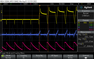
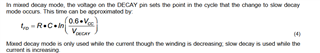
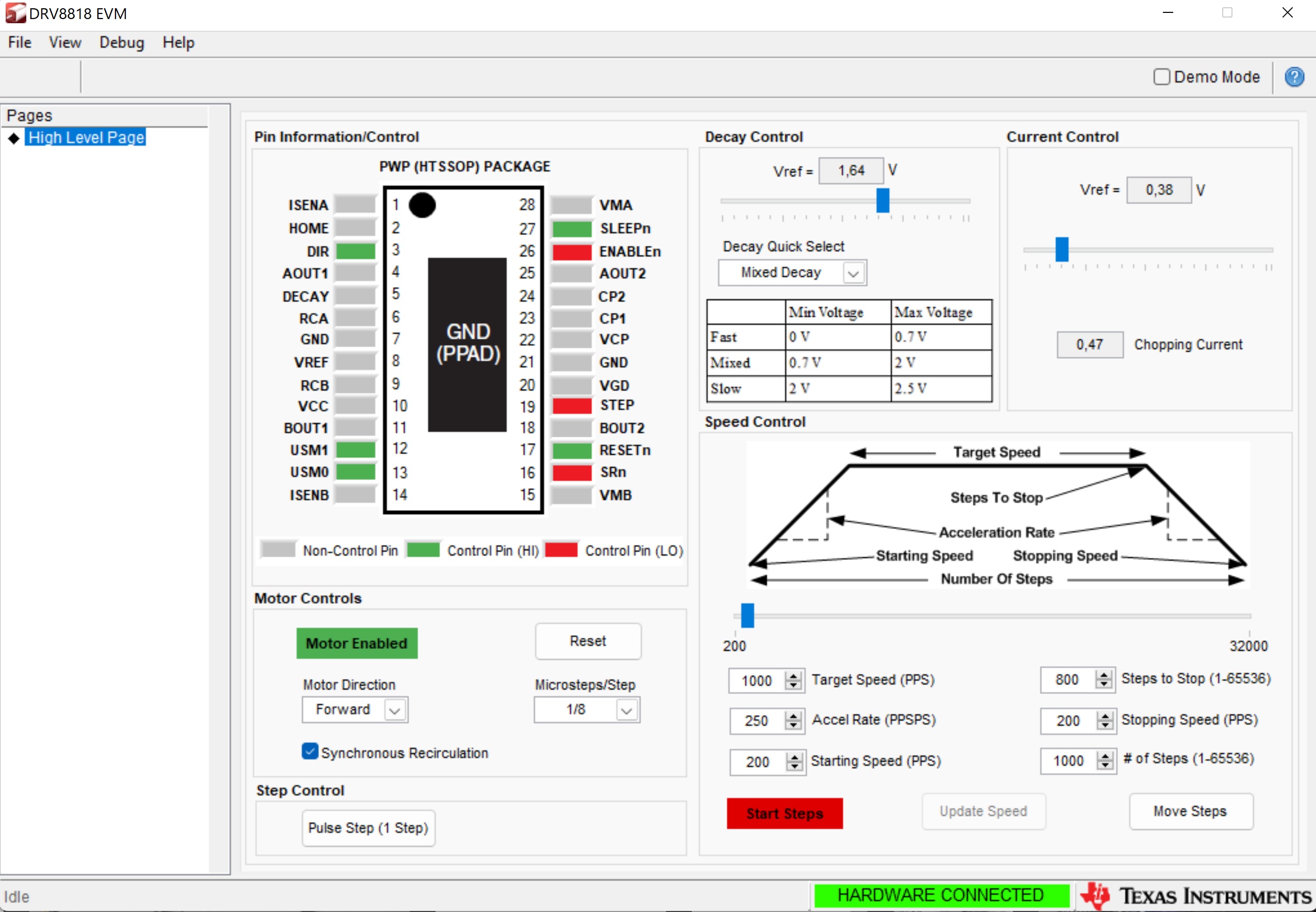
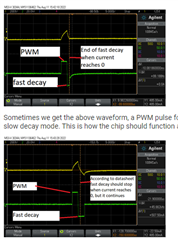
Measurements with the scope showed us jitter on the hold pulses to the motor coils.The jitter had to be related to the current measurement part of the motor driver, because the motor is not moving, so the step sequencer is not active. We measured the old situation with A3977SLP and compared our results with DRV8818 results.
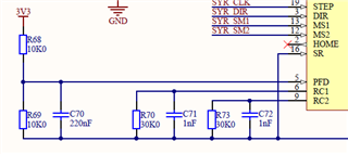
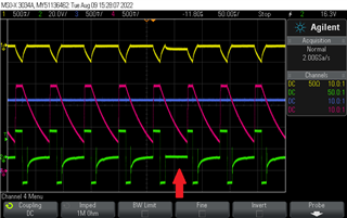
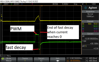
We saw a difference in blanking time. Based on our measurements, we narrowed down the cause of the sound to the RC networks RC1 and RC2 on pins 6 and 9 of the motor driver in combination with the filter capacitors. We changed RC1 and RC2 to 56K and 820 pF. The blanking time is exactly the same as the A3977SLP..These seemed fine on several boards we tested. The noise was gone and we gave green light to modify our stock.

Today we received a first batch of 20 PCB's. Four PCB's passed all tests but the fifth PCB had the same unusual noise.

We can get rid of the noise connecting another motor (same type and specs as the other).
Right now we are staring into the dark. We know for sure that we tuned the motor circuit correctly.
But what is wrong? We never had problems with the A3977SLP.
What is different in the DRV8818 to generate this unusual and unwanted noise?
We have a stop shipment, so we need a fix for it very urgently. 
Any help is appreciated.

Thanks 
Harm

  • Hi Harm,

    Can you provide a screenshot of the driver schematic (can share via private message if you desire). Also, please share the output current and voltage waveform.

    Regards,

    Pablo Armet

  • Hi Pablo,

    The parts not entirely according the most recent status.
    We changed R70 and R73 to 56K, and C71 and C72 to 820pF to obtain the same blanking time as with Allegro (blanking time is 1.3 us) .
    C45 and C44 100nf are removed.

    The holding current is set to 200mA.
    Is the holding current too low for this setup? Is the RC network too critical? Anything else?

    Thanks for your help.

    regards,

    Harm

  • Hey Harm, 

    Those RC values for RCA/RCB seem good, right in the middle of the datasheet 6.7 Motor Driver Timing Switching Characteristics.  Try replacing C71 and C72 since the capacitor affects the blanking time and off time - I'm wondering if one of the caps is near the top of the usual ±10% accuracy and if that's enough to throw it off.  Unlikely, but easy to replace two capacitors.  Maybe also try a lower value like 680pf or lower.  

    Pablo will also look at this tomorrow and give his thoughts.  

    Thanks, 

    Jacob

  • Hi Jacob,

    Thank you for your response.
    We initially had a 430pF capacitor but with this value the issue was even bigger than with 820pF. We use ±5% capacitors not the usual ±10%.

    Yesterday we increased the holding current from 200mA to 300mA. This made the unusual unwanted noise to disappear. Even under extreme conditions (high ambient temperature) the DRV8818 current regulator remains stable and motor makes no noise.

    Right now we are looking for an explanation. It seems as if the DRV8818 has difficulties regulating the holding current at 200mA.

    Can you confirm this? Have you seen this behavior before?

    Thanks.
    Harm

  • Hey Harm,

    I looked around for other E2E posts about it and I did find another post discussing a 190-315mA holding current they found.   https://e2e.ti.com/support/motor-drivers-group/motor-drivers/f/motor-drivers-forum/445752/stepper-driver-8818-has-minimum-holding-current  I don't think this is very helpful in our case, but read through the thread solution about average current vs phase current.  

    Also, what is the bulk capacitance for your system VBB1 & VBB2?  I'm sure you have it, it just isn't on the schematic above.  

    Regards,

    Jacob

  • Hi Jacob,

    I couldn't find the VBB1 and 2 you are referring to. I found it in for example DRV8801 but not in the DRV8818.

    We are still struggling with this problem. Wet thought we solved the problem by increasing the holding current for the motor with the unusual noise. But now we have it also in a motor that requires a high holding current (1.0 A).
    We suspect a problem in the DRV8818. The DRV8818 is not working properly in the mixed decay mode so it seems.
    When we select fast decay the problem with unusual noise is gone. When we select slow decay the noise is also gone but the current increases.

    Are you aware of mixed decay problems?

    Do you also have a description for the batch/date code on the chip?

    Thanks
    Harm

  • Hi Harm,

    Have you tried using a different motor or different driver? Does the issue show up?

    Are you aware of mixed decay problems?

    Not in this specific case. in some motors and load conditions, it mixed decay may not be the best decay mode to use. If slow decay eliminates the noise, it could mean the mixed decay mode is the culprit. Can you provide a waveform with fast or slow decay.

    Do you also have a description for the batch/date code on the chip?

    This information in on the lot trace code on the chip marking.

    Regards,

    Pablo Armet

  • Hi Pablo,

    I will provide waveforms if still necessary. I just wanted to discuss a change that seems to solve all our problems.
    We changed the capacitor connected to the decay pin from 220nF to 100nF. Now all the disturbances we saw in the current regulation and the unusual noise is gone. We are now looking for a logical explanation. Hope you can help and provide one.

    Is it correct to say that this is a valid solution?

    Thanks.

    Harm

  • Hi Harm,

    Thank you proving the information.

    In the datasheet, 100nF capacitance is recommended at the DECAY pin for proper functionality. Please use this value at the DECAY pin instead of 220nF.

    As explained in section 7.3.3 of the datasheet, when DECAY voltage is between 0.21xVCC and 0.6xVCC, the decay mode is set to MIXED decay and the DECAY voltage sets the point at which it changes from fast to slow decay (t_fd). Higher capacitance on DECAY pin may be causing this t_FD value to be higher. It would be a good idea to look at the output current and DECAY voltage with 100nF and 200nF to see if this is the case.

    Regards,

    Pablo Armet

  • Hi Pablo,

    With the 100nF decay capacitor we thought we found a solution. We thoroughly tested this solution and were really confident about this change.

    But now the 16th instrument that was assembled in the factory gave the same unusual noise again.
    Right now we are gazing into the dark again and don't know what to do to solve this issue.

    Below you see a scope capture for a motor with the unusual noise. There is no clock applied, motor is kept in position by means of holding current.

    channel 1 = current
    channel 2 = differential probe over motor coil
    channel 3 = voltage on the decay pin
    channel 4 = voltage on the RCB pin

    In our opinion the DRV8818 does not correctly handle the mixed decay mode, you can see it in the different signals in the scope capture above.
    Mixed decay is only handled correctly in above image see red arrow. In all situations the DRV8818 only applies fast decay.
    What could be the reason? Do you know what is wrong?

    Hope you can help.

    Thanks.
    Harm

  • Hi Harm,

    Thank you for providing the information.

    I will have to look into this in more detail with our design team. Please give us another 24-48 hours.

    Regards,

    Pablo Armet

  • Hi Pablo,

    Looking forward hearing from you and/or your design team.

    Thanks.
    Harm

  • Hi I'm a collegue of Harm and I would like to add some extra measurements we just did. We increased the voltage on the DECAY pin in the hope that the problem would go away. Unfortunately it didn't we could only make the noise stop by increasing the decay voltage to the point that the chip is in fast slow decay mode only. We also tried lowering the voltage, again the noise stayed until we lowered the voltage to the point that the chip was completely in fast decay mode.

    Next we had a closer look at the two waveforms that the chip is producing: CH2 is the current through the motor winding, CH3 is the voltage across the motor winding, measured with a differential probe.

    normal

    Sometimes we get the above waveform, a PWM pulse followed by fast decay until the current reaches zero. After fast decay, the chip continues in slow decay mode. This is how the chip should function according to the datasheet.

    strange

    Other times the chip alternates to the above waveform. After the PWM pulse, the fast decay mode stays active until the current has actually gone below zero. It is as if the fast decay mode is overshooting. The chip is jittering between these two modes.

    Another thing we noticed is that we noticed is that the jitter goes away completely if we connect a motor with a higher inductance.

  • Hi Jan,

    Thank you for the extra information.

    Another thing we noticed is that we noticed is that the jitter goes away completely if we connect a motor with a higher inductance.

    This is very useful information. It is more clear to me now that the noise is happening when the decay mode is alternating between mixed decay mode (upper waveform) and fast decay (lower waveform). When you set it to either always fast or slow decay, the noise goes away as it remains fixed.

    The higher inductance motor prevents the current from decreasing too fast and overshooting. I'm not sure if this is the exact reason for the abnormal decay mode but it is a good lead. I will relay this information to our design team.

    Can you provide the inductance of the motor with the noise and the motor with no noise?

    Regards,

    Pablo Armet

  • Hi Pablo,

    I measured the most problematic motor, it has an inductance of around 860micro Henrys per motor coil. When we swapped this motor with another motor that has 1700microHenry inductance, the jitter stopped and the waveforms were as we expected them based on the datasheet.

    Another thing we noticed is that the problem only occurs when the motor is stopped in those parts of the microstepping table where the current is lowest (but not zero). 

    In total our instrument has 7 motors.

    1 motor has around 860 microHenry coils (This motor gives the most problems).

    1 Motor has about 1000 microHenry coils. This motor is the second worst in terms of observed problems.

    2 motors have ~6000 microHenry coils. No problems observed with these motors.

    2 motors have ~1700 microHenry coils. Very few problems observed with these motors. Production personnel claim they can feel vibrations while holding onto the motor axles. We have not been able to reproduce this in the lab.

    1 motor has ~1700 microHenry coils. It is different from the other motors because the Vref is 0V when the motor is stopped. Some problems observed with this motor. We realize that having Vref at 0V is a bad idea and will adress this problem.

    The motor drivers are operated on a 24V power supply. I tried running the board on a variable power supply. When I dropped the voltage to 20V the jitter decreased significantly, but did not go away completely.

    Best regards,

    Jan

  • Hi Jan,

    Another thing we noticed is that the problem only occurs when the motor is stopped in those parts of the microstepping table where the current is lowest (but not zero).

    Is it on the increasing or decreasing current steps of the current waveform? This is useful information. Typically the lower the current step the lower the accuracy of the current sensing. At what steps did the noise issue started to appear?

    I will continue to investigate this more. I think we may have enough clues to figure out the cause of the jitter. In the meantime, I have a question. If slow decay and fast decay does not produce the noise, is there a reason why you still want to use mixed decay?

    Regards,

    Pablo Armet

  • Hi Pablo,

    Pablo Armet said:
    Is it on the increasing or decreasing current steps of the current waveform?

    The problem only occurs on the decreasing current steps. This is because the chip only uses mixed decay on the decreasing part of the table (see page 12 of the DRV8818 datasheet).

    Pablo Armet said:
    is there a reason why you still want to use mixed decay?

    Mixed decay is needed to maintain proper current waveforms during microstepping.

    I have some additional information. We have purchached an evaluation board for the chip,  DRV8818EVM. My collegue is able to reproduce the problem on the evaluation kit. He is using the same motors that are in our instrument.

    Regards,

    Jan Visser

  • My collegue provided me with the Eval board settings that he used for reproducing the jitter. First the settings used for the 1000uH motor:

    Next for the 850uH motor:

    Hope this helps.

    Best regards, Jan Visser

  • Hi Jan,

    It is good that you were able to reproduce with the EVM. This rules out the possibility of the root cause being in your system.

    I noticed that the only difference between the two motors in the VREF voltage for the current chopping limit. If you set the shopping current on the 850uH motor to 0.93A (same as 1000uH motor) does the jitter go away?

    Regards,

    Pablo Armet

  • Hi Pablo,

    If you set the shopping current on the 850uH motor to 0.93A (same as 1000uH motor) does the jitter go away?

    The short answer is yes. We have tried varying the chop current from 0 to 2A with all of the motors. We found that as long as mixed decay is enabled, every motor has at least 2 chop settings where jitter takes place. The jitter takes place at a different setting for each motor. It seems that motor inductance influences at which setting the jitter occurs.

    Now it is easy to simply select a chop current for each motor where jitter does not occur. However that is not entirely satifactory. It merely removes the symptom, but does not address the cause. What we really want to know is 'why does this design jitter?'. Once we have an answer to that question we can make an informed decision about wether the proposed solution really permanently removes the problem.

    We have had several instances were we thought that changing a capacitor or RC combination would make the problem go away, only for it to return after several more boards were produced.

    The chop settings for the motors are chosen based on mechanical constraints e.g. the required torque and how hot the motor is allowed to get. Choosing new chop settings to remove jitter means having to re-test a large part of the instrument to verify that everything still works correctly. So, yes we can change the chop settings but it will require a significant amount of work. Therefore we want to be absolutely sure that the problem does not return after 1000 new boards have been produced.

    Best regards,

    Jan Visser

  • Hi Jan,

    Thank you for answering my questions.

    I believe the best course of action here is to ask our design engineers to help understand this jitter. The question to ask is whether this is expected behavior and why is it occurring under specific chopping limit and motor inductance. And obviously we'll like to know what can be done to offset the jitter since changing chopping current will be a lot of work for you.

    I will reach out to our team and will get back to you with a response with 48 hours.

    Thanks in advance for your patience.

    Regards,

    Pablo Armet

  • Hi Jan,

    I am still looking into this issue. Please give me another 48 hours. Thank you in advance for your patience.

  • Hi Jan,

    We are still investigating. Please give us more time. I will get back to you by the end of the week at the latests.

    Thank you in advance for your patience.

    Regards,

    Pablo Armet

  • Hi Pablo,

    Just let us know if you need any more data on this subject. We've measured just about every part of the circuit by now.

    Best regards,

    Jan Visser

  • Hi Jan,

    Yes. Will do.

  • Hi Pablo,

    Is there any news yet?

    Best regards,

    Jan Visser

  • Hi Jan,

    Apologies again but we are still looking into this. I will get back to you with a final answer within 48 hours.

    Regards,

    Pablo Armet

  • Hi Pablo,

    Do you have a final answer or a solution for us?

    Thanks.

    Harm

  • Hi Harm,

    Unfortunately we don't have a concrete explanation. What we suspect is the likely cause is the current, during the fast decay, is decreasing too fast in low inductance motors causing the current to decrease to zero and go in the opposite direction before TOFF expires (like what is shown in second waveform below). This would explain why no noise is present in higher inductance motors. What we recommend is decreasing the TOFF by adjusting RCA and RCB R&C. 

    Apologies that we don't have a clear solution. If the above recommendation does not work, let me know and we can brainstorm other ideas.

    Regards,

    Pablo Armet

  • Hi Pablo, besides RCA and RCB we also tuned the current holding current to get rid of the noise. Jan already explained this action. We did not succeed to take it away completely. We still have 10 to 15% that produce noise and therefor do not pass the test.

    Tuning RCA and RCB resulted in a lower chopper frequency, approx 15kHz which has a major disadvantage. When motor is activated/in standstill with holding current you can hear a high noise.

    Right now we only see one solution for this specific project. We have to re-design our boards to be able to set the decay mode to fixed (either slow or fast decay) when motors are active/in standstill with holding current. This is of course not the solution we were waiting for. Not only time wise but it also introduces extra costs.

    For other projects we don't have this fixed decay option due to the lack of free IO pins. Going back to the Allegro A3977SLP-T is the only option but due to the current market situation this will also increase the costs.

    Or do you see another solution?

    Regards,
    Harm