This thread has been locked.

If you have a related question, please click the "Ask a related question" button in the top right corner. The newly created question will be automatically linked to this question.

DRV2605L: Rated voltage

Part Number: DRV2605L
Other Parts Discussed in Thread: DRV2605

I have some questions about increasing the amplitude of LRA using DRV 2605L haptic motor driver.

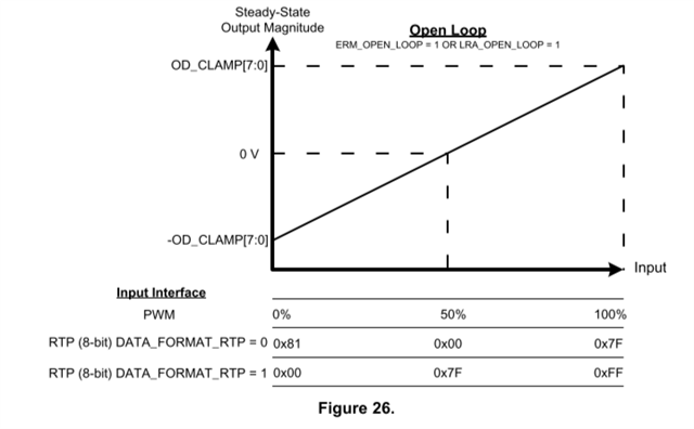
Firstly, when I saw the datasheet of it, I think that it is available to adjust the rated-voltage and OD_clamp voltage to increase the amplitude of LRA. 

Related to this, I have some questions as below : 

(1) I just want to know the difference between adjusting rated-voltage and waveform library effects list.

To be specific, when I tried to use the list (effect id no =1, strong click-100%), I just want to find out the solution to increase the amplitude of LRA. 

For this reason, I want to figure out the definition of "100%". 

(2) Using Arduino and LRA (vibration motor), is it possible to increase the rated-voltage over 5V ? 

  • Hi Kihun,

    the RATED_VOLTAGE value will define what 100% strength is for any of the waveform effects. this means that for a 100% strength waveform it will overdrive the LRA to OD_CLAMP voltage momentarily and then the output will decrease to the RATED_VOTLAGE for the duration of the waveform. 

    If you want to increase the vibration strength of the LRA you can increase the rated voltage.

    Since the maximum VDD on this part is ~5.2V,  then you wont be able to increase the RATED_VOLTAGE above 5V

    Regards,

    Arthur

  • Hello Brown, 

    According to DRV2605L datasheet, there are various graph to describe how to vibrate for each waveform library. I am just wondering how to get these graphs 

    to describe the vibration acceleration. 

    Is there any reference you may suggest? 

  • Moreover, according to your DRV2605 Setup Guide datasheet, it said that convert the rated voltage from the LRA data sheet to an "average of the absolutes" voltage using the following equation. I just want to know the value for f(LRA). Is it from the LRA data sheet? I wonder whether it means the resonant frequency or not. 

  • Hi Kihun, 

    It is not possible to say what the acceleration will be in your system, however you can measure the acceleration the same as it is shown in the datasheet using this accelerometer EVM. https://www.ti.com/product/DRV-ACC16-EVM/part-details/DRV-ACC16-EVM?

    F(LRA) is the resonant frequency of the LRA. or more specifically it is the driving frequency coming out of DRV2605L. which should be the same as the resonant frequency,

    Regards,
    Arthur

  • About auto-calibration, the datasheet said that "auto-calibration compensates for the variation and also performs scaling for the desired actuator according to the specified rated voltage and overdrive clamp-register settings." And based on your answer, if I want to change the vibration strength of the LRA, I could make the RATED_VOLTAGE various value. Is it right? 

    And also, do I need to process auto-calibration for just varying the strength? 

    I am just wondering whether there is any reference about the auto-calibration code. 

  • Hi Kihun,

    Sorry for the delay; Arthur is evaluating your question and will give you a response by the end of the day.

    Thank you,

    Jeff

  • Hi Kihun.

    Yes if you want to increase the maximum voltage the DRV2605L device will drive to the LRA then you can increase the Rated_Voltage. you should also perform auto calibration after changing the rated voltage

    Regards,
    Arthur

  • Before changing the reated_voltage value, I just performed auto calibration as below : 

    I used LRA actuator and DRV2605L motor driver. 

    #include <Wire.h>
    #include <Sparkfun_DRV2605L.h>

    SFE_HMD_DRV2605L HMD;
    uint8_t feedback_val = 0;
    const int f_lra = 240;
    float v_rms = 1.2;
    byte dr_time;

    void setup(){

    Serial.begin(9600);
    Wire.begin();
    HMD.begin();
    HMD.Mode(0x07);
    set_feedback();
    HMD.writeDRV2605L(MODE_REG,feedback_val);
    float sample_time = 300 * pow(10,-6); // sample time, default value 300us
    float v_avg_abs = v_rms* sqrt(1-(4*sample_time+300*pow(10,-6))*f_lra);
    uint8_t ratedv_val = (uint8_t)((v_avg_abs*255)/5.3);
    HMD.writeDRV2605L(RATEDVOLT_REG,ratedv_val);
    HMD.writeDRV2605L(OVERDRIVECLAMP_REG,0x89);
    set_ctrl1_val();
    HMD.writeDRV2605L(CONTROL1_REG,dr_time|0x80);
    HMD.writeDRV2605L(CONTROL2_REG,0xF5);
    HMD.writeDRV2605L(CONTROL3_REG,0x80);
    HMD.writeDRV2605L(GO_REG,0x01);

    }

    byte set_feedback(){

    feedback_val |= (1<<7); // set LRA mode
    feedback_val |= (3<<4); // set brake factor as 4x
    feedback_val |= (1<<2); // set loop gain as medium
    feedback_val |= (1<<1); // set BEMF_gian as 20x

    return feedback_val;
    }

    byte set_ctrl1_val(){
    uint8_t ctrol1_val = 0;
    float period_lra = 1.0/f_lra;
    uint8_t dr_time = (uint8_t) (((period_lra * 1000.0 / 2.0) -0.5) / 0.1);

    return dr_time;
    }

    void loop(){
    uint8_t status = HMD.readDRV2605L(STATUS_REG); // read the Diag_Results bt in the status register
    uint8_t Acalcomp = HMD.readDRV2605L(COMPRESULT_REG); //auto_calibration compensation result
    uint8_t Acalbemf = HMD.readDRV2605L(BACKEMF_REG); //auto_calibration Back-EMF compensation result
    Serial.println("DRV2605L status");
    Serial.println(status);
    Serial.println(Acalcomp);
    Serial.println(Acalbemf);

    return (status&0x08)==0;

    }

    I just got the value for status, auto-calibration compensation result and auto-calibration back emf compensation result as 

    224, 12, and 108. I just want to confirm whether these are suitable values or not. And if I got these results, do I need to do next step? 

  • Hi Kihun,

    I do not see any issue with the auto calibration results. 

    Status register = 224 is just indicating that the device you are using is DRV2605L. Regarding the status register the most critical bit is the DIAG_RESULT bit. if this bit is set then autocalibration has failed. if it is not set then auto calibration is successful.

    You can now proceed with changing the Rated_Voltage value and re run auto calibration. as long as DIAG_RESULT is not set then the calibration was successful

    Regards,

    Arthur

  • Hello Brown, 

    I just want to know how to increase the rated-voltage. If I use the open-loop mode, I just need to adjust the value for "OD_CLAMP[7:0]" or is there any recommendation to refer to? 

    And also, I just want to know the difference between open-loop mode and closed-loop mode. What is the feedback for closed-loop? 

  • Additionally, i have a little bit confused about real-time playback mode (RTP). 

    According to its datasheet and Figure26 (as below), when I set RTP register (0x02), for example 0x7F, 

    (1) it means that I drive the actuator with the 100% overdrive voltage that I set. Is it right? 

    (2) Then, if I don't set the value for OD_CLAMP[7:0], what is the voltage that actuates LRA? 

    (3) Also, when I use RTP mode, what is the value for frequency? I think that the value is the resonant frequency that each LRA has, is it right?

  • Hi Kihun,

    in closed loop mode the device is periodically sampling the Back EMF from the LRA to track the resonant frequency. 

    in open loop mode there is no feedback and the device is not tracking the frequency. it is driving the LRA at the frequency in the DRIVE_TIME register field. 

    section 8.5.2.1, and 8.5.2.2 of the datasheet gives the formulas to convert the register values of OD_CLAMP and RATED_VOLTAGE for both open and closed loop mode. 

    (1) it means that I drive the actuator with the 100% overdrive voltage that I set. Is it right? 

    Yes, if DATA_FORMAT_RTP = 0 then 7f equals to 100% of the OD_CLAMP voltage.

    (2) Then, if I don't set the value for OD_CLAMP[7:0], what is the voltage that actuates LRA? 

    OD_CLAMP has a default value of 0x8C

    (3) Also, when I use RTP mode, what is the value for frequency? I think that the value is the resonant frequency that each LRA has, is it right?

    the frequency in closed loop mode is tracked and lives in OL_LRA_PERIOD register field

    in open loop mode it is driven at the DRIVE_TIME frequency

    Regards,

    Arthur

  • Thank you for your kindly response. 

    I just want to double check the process to set LRA with DRV2605L. 

    Before starting to drive LRA for my research project, I need to do auto-calibration. Then, do I need to do it again whenever I start driving motor? 

    It means that after getting the calibration's values and there is no change in my system, do I need to re-calibrate before running the code that drives the actuator.

    Secondly, in the main code, do I need to always write the initialization mode before running into driving actuator code? 

    Or, it is similar as the calibration process? 

  • Hi Kihun,

    you do not need to run the autocalibration every time. It can be done just once, and then at power-up you can program the registers that where found previously from auto calibration.

    After writing the necessary values you can then proceed with driving the acctuator.

    Regards,

    Arthur

  • Thank you how about the initialization? 

    I am just curious about it now.

  • Hi Kihun,

    I am not exactly sure what you refer to when you say "initialization" 

    But the basic flow that should be done each time the device is powered on is

    1) program registers associated with the autocalibration results (that where found and recorded previously)

    2) enter the desired playback mode

    3) playback waveform

    OR~~~~~ (If you did decide to run autocalibration each time the device is powered)

    1) program the inputs to the auto calibration engine

    2) perform the autocalibration routine and ensure that DIAG_RESULT bit is NOT set.

    3) enter desired playback mode

    4) playback waveform