This thread has been locked.

If you have a related question, please click the "Ask a related question" button in the top right corner. The newly created question will be automatically linked to this question.

DRV8837: Design review

Part Number: DRV8837
Other Parts Discussed in Thread: DRV8838, DRV8210

Dear TI Technical Support Team,

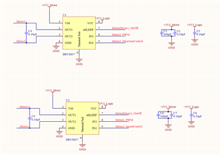
I am designing a board that will be used to control direction and speed of 2xDC hobby motors (3-9V, 110RPM). Two of them can draw at most 250-300mA under full load. I decided to use  DRV8837 to control DC motors. I have attached the schematic. In the schematic, C1 and C6 are 100uF 16V electrolytic capacitors. In the pcb layout, I will place them as suggested in datasheet. I have following questions. If possible, could you please answer them.

1. From the datasheet and similiar threads in the forum, what I understand is that, to control/change the direction I need to apply logic 0 or 1 to IN2 input of DRV8837, to control speed using pwm I need to apply pwm signal to IN1 input, and to shutdown the motor driver I need to apply logic 0 to all three inputs (nsleep, IN1 and IN2). Is this correct?

2. I put 100nF 50V ceramic capacitor between OUT1 and OUT2 of motor driver to reduce noise. Do you recommend it?

3. Do I need external flyback/clamp diodes for back emf protection when using DRV8837?

4. The board is powered from 1S Lipo battery. I am using buck converter to convert input voltage to 3.3V motor voltage. Do you have some other recommendations to protect +3V3_Motor power path or it is enough to put some bulk capacitor on VM line?

Thank you in advance for your help,

Best regards,

Ahmet
  • Hi Ahmet,

    1. From the datasheet and similiar threads in the forum, what I understand is that, to control/change the direction I need to apply logic 0 or 1 to IN2 input of DRV8837, to control speed using pwm I need to apply pwm signal to IN1 input, and to shutdown the motor driver I need to apply logic 0 to all three inputs (nsleep, IN1 and IN2). Is this correct?

    Not quite. to change direction the IN1 and IN2 need to be switched. For example, if IN2=0 and IN1=PWM, to change direction, IN1=0 and IN2=PWM. An easier control interface for changing direction and speed of motor is called "Phase/Enable". The DRV8838 is the phase/enable version of the DRV8837 but we have a newer device, the DRV8210, which is capable of both PWM and phase/enable control interface. This FAQ explains the differences between the two control interfaces.

    2. I put 100nF 50V ceramic capacitor between OUT1 and OUT2 of motor driver to reduce noise. Do you recommend it?

    This is fine. Just ensure it is not too much capacitance such that the added inrush current triggers OCP.

    3. Do I need external flyback/clamp diodes for back emf protection when using DRV8837?

    This is optional. It is highly recommended for high power motors that can generate very high energy due to BEMF. In your case, I don't think it is needed.

    4. The board is powered from 1S Lipo battery. I am using buck converter to convert input voltage to 3.3V motor voltage. Do you have some other recommendations to protect +3V3_Motor power path or it is enough to put some bulk capacitor on VM line?

    The converter should provide a steady 3.3V so just adding a decoupling capacitor on VCC should be enough. If you are very concern about the 3.3V line jumping in voltage, you can add a clamping diode.

    Regards,

    Pablo Armet

  • Hi Pablo,

    Thank you very much for your help.

    Best regards,

    Ahmet