This thread has been locked.

If you have a related question, please click the "Ask a related question" button in the top right corner. The newly created question will be automatically linked to this question.

DRV8452: Setting of initial current on ATQ

Part Number: DRV8452

Hi support team.

I have a question regarding the auto torque parameter setting example in the datasheet.
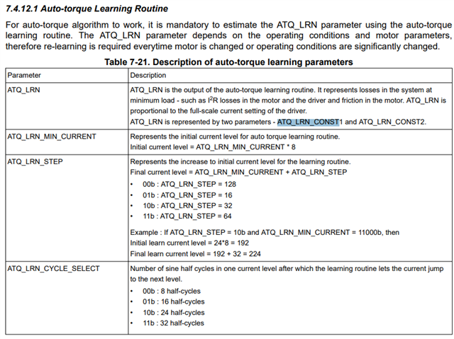
I found the following in the datasheet.
I have set the initial current setting to 740mA, but isn't it possible to set 740mA?
Initial current level = ATQ_LRN_MIN_CURRENT x 8, and ATQ_LRN_MIN_CURRENT has a maximum value of 31, so the maximum initial current level setting is 248.

If my understanding is wrong, could you tell me the setting parameters for the initial current level 740mA?

Best regards,

Higa

  • Hey Higa,

    The level settings you reference are in proportion to the Full-Scale Current setting.  

    The EVM User's Guide describes this very well in step h. Auto Torque where the Full-Scale Current is set to 2A: 

    Configure the minimum and maximum current limit values in “Loop Regulation” section. These are 8-bit integer values, 0 to 255 in decimal. Set the minimum current limit value to 48 which will be equal to (48/256) * 2 A or 375 mA. With 375 mA drive current, this stepper motor will have sufficient torque to run with a light load without losing steps or stalling. This is the criteria for choosing the minimum current limit value in an application. Set the maximum current limit value to 192 which will be equal to (192/256) * 2A or 1.5A. A higher maximum value can be chosen if needed by the application. Auto torque will allow over driving the motor for short periods of time during transient higher load torque.

    The datasheet discusses the relationship with full-scale current a lot in 7.4.12 Auto-torque Dynamic Current Adjustment if you ctrl+f for Full Scale.

    Regards,

    Jacob

  • Hi Jacob-san

    Thank you for answering.

    I have some questions about your answer.

    - What is ctrl+f?

    - I don't still quite understand what ATQ_LRN_CONST1&2 is. 
     What is the unit of ATQ_LRN_CONST?
     Does ATQ_LRN_CONST1 mean the full-scale current value at no load?
     If YES, under what conditions is ATQ_LRN_CONST2 a full-scale current value?

    Best regards,

    Higa

  • Hey Higa-san,

    Sorry for the confusion, "ctrl+f" just means searching in the datasheet to find all instances of "Full Scale"

    Here's page 41 that describes the parameters:

    They are a value from 0 to 256.  I don't think it specifically has a unit - it is in relation to the full-scale current set, above which OCP would trip.  It learns the current at the beginning of testing (low torque, stored in ATQ_LRN_CONST1), and then learns it at the final current level as described with the ATQ_LRN_STEP and stores the value into ATQ_LRN_CONST2.  

    Regards,

    Jacob

  • Hi Jacob-san

    Thank you for your kind support.

    I have additional questions below.

    We are currently evaluating with EVM.
    It seems that the values of CONST1 and CONST2 obtained from automatic torque learning with EVM are inconsistent.
    The initial learning current was set to 4, the current step for learning to 128, and the current cycle for learning to 8.
    The results obtained are 38 for ATQ_LRN_CONST1 and 87 for ATQ_LRN_CONST2.
    The initial learning current level is 32, which is 128 steps, so 32+128=160.
    The results obtained were CONST1=38 and CONST2=87.
    I don't understand the relationship between the initial current level and ATQ_LRN_CONST1.

    Q1 : How is ATQ_LRN_CONST1 calculated?
    Q2 : At this time, IFS1 is 2*(48/256)=375mA and IFS2 is 2*(192/256)=1.5A?

    Q3 :I set it in the GUI as follows and obtained the current waveform (phase A) when the motor was unloaded and when it was loaded.
      When the motor was rotating with no load, the maximum current limit was 1.5A when a load was applied with the minimum current setting of 380mA.
      At this time, the Auto torque count Overflow or Auto torque count Overflow indicator turned red.
      Although the indicator is red, the load on the motor is still controlling the full-scale current. Is this setting correct?
      The motor is rotating at 1/16 step 6000pps.

    Please refer to the attached file.

    Auto torque function.xlsx

    Best regards,

    Higa

  • Higa san, See my comments in blue.

    It seems that the values of CONST1 and CONST2 obtained from automatic torque learning with EVM are inconsistent. Did you mean not related to the min and max current settings? CONST1 and CONST2 are internally computed by the algorithm. It is proprietary algorithm. It is a computation of I*R losses in the motor windings and has a linear relationship with the set full-scale current. It is provided as an indication as well as to copy and store to multiple drivers devices' Registers in production such that Auto torque can be used in the end application without a learning procedure. They can vary slightly but never totally off from one learning to another for the same motor under the same current setting conditions.   
    The initial learning current was set to 4, the current step for learning to 128, and the current cycle for learning to 8. For a min current value 48 you can set this to 8 so initial learning current will be 8*8 = 64 is higher than 48. 
    The results obtained are 38 for ATQ_LRN_CONST1 and 87 for ATQ_LRN_CONST2.
    The initial learning current level is 32, which is 128 steps, so 32+128=160. With min setting changed to 8, it will be 64+128 = 192 equal to max current limit.
    The results obtained were CONST1=38 and CONST2=87. Looks fine, it depends on the motor and its current settings.
    I don't understand the relationship between the initial current level and ATQ_LRN_CONST1. This is internally computed automatically with a learn procedure. The user does not have any control over it other than the initial current and current steps settings. Learn must be done with motor spinning unloaded and Auto torque loop closed, Kp > 0 (typical value = 1). 

    Q1 : How is ATQ_LRN_CONST1 calculated? It uses a TI proprietary algorithm and is provided as a black box solution to the user. The values are computed automatically with a learn procedure. 
    Q2 : At this time, IFS1 is 2*(48/256)=375mA and IFS2 is 2*(192/256)=1.5A? You are correct.

    Q3 :I set it in the GUI as follows and obtained the current waveform (phase A) when the motor was unloaded and when it was loaded.
      When the motor was rotating with no load, the maximum current limit was 1.5A when a load was applied with the minimum current setting of 380mA. Please double check. It should be the opposite. When the motor spins unloaded it should run with the minimum current setting and when the motor spins fully loaded (nominal application load + margin torque) it should run with maximum current setting assuming Auto torque is enabled and setup correctly.
      At this time, the Auto torque count Overflow or Auto torque count Overflow indicator turned red. With an unloaded spinning motor when auto torque is enabled and configured correctly Count Underflow bit will be set (red) indicating Auto Torque Count < its lower limit setting and with slightly higher load than the fully loaded spinning motor Count Overflow bit will be set (red) indicating Auto Torque Count > its upper limit setting.      
      Although the indicator is red, the load on the motor is still controlling the full-scale current. Is this setting correct? Yes, correct. The upper limit(UL) and lower limit(LL) must be set in such a way the motor is running with an Auto Torque Count between the UL and LL. A red indication simply means limit was exceeded and there may not be more room. LL value must be chosen such that the motor does not stall or lose steps with the least load condition and UL value must be chosen such that the motor does not stall or lose steps with the most load condition in an application. Under nominal load operation the motor spins with auto torque operating within the band set by LL and UL. Auto torque allows running above and below the band while doing so will set the corresponding bits to let the user know it is operating outside the set limits. If the Auto torque allows the motor to work fine outside the set limits it means max and min current limits can be further optimized (reduced) to achieve maximum power savings using auto torque.   

    In your setting UL = 4 and LL =3 makes an extremely narrow band of operation. Please refer the datasheet for how to select UL and LL settings. Try values like 15 and 5 for these limits. If the unloaded current does not go to the minimum value automatically after removing the load increase the LL. If the motor stalls when loaded decrease the UL. Try sudden (transient) loads.  
      The motor is rotating at 1/16 step 6000pps. This is totally fine as long as the motor specs and VM power supply supports the requirement.

    I hope this gives you clarity on auto torque functionality.

    Regards, Murugavel

  • Hi Murugavel-san

    Thank you for your kind explanation.

    I understood well.

    Thanks!

    Best regards,

    Higa

  • Thanks, have a nice day!