This thread has been locked.

If you have a related question, please click the "Ask a related question" button in the top right corner. The newly created question will be automatically linked to this question.

DRV8812: Device functional query

Part Number: DRV8812

Hi Team,

My customer is planning to use DRV8812 in one of the medical project and having below queries to proceed. Can you please help address below queries. 

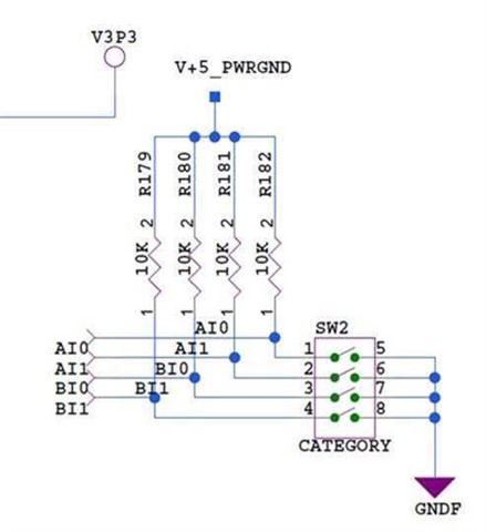
1) Does the pins (AI1, AI0, BI1, and BI0) control the motor current as well?  Planning to have a dedicated circuit for Vref generation(different ref voltages) and sense resistors connected. Does these pins AI1, AI0, BI1, and BI0 do the same job as Vref circuit does? Currently used a DIP switch to configure the current scaling settings. See below,

2. Fault condition: Can you provide suggestions on how to implement a self-recovery circuit during a fault condition? In case of a fault condition , can the nFAULT pin be connected to RESET pin with a RC circuit (as OCP time we understand is 3.8ms, we can have a RC ckt for greater than this duration).

3. Can the signals like NSLEEP, DECAY and RESET and Bridge control setting pins( AI1, AI0, BI1, and BI0) , PHASE and ENABLE  can be connected to a 5V through a pull-up?

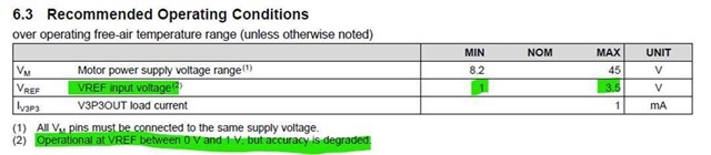
4. VREF: As per the recommended Operating conditions, VREF has a min of 1V. Less than this will have the accuracy degraded. Question: What is the worst case voltage level where the voltage degradation will affect the system performance? (Design constraint is current control <1V VREF)


 Regards, Shinu. 


  • Hey Shinu,

    1) Does the pins (AI1, AI0, BI1, and BI0) control the motor current as well? 

    Per section 7.4.2 Current Regulation of the datasheet, changing those pins will change the chopping current threshold.  VREF and the sense resistor value set the overall full-scale (100%) chopping current, then these pins can be used to select the relative current on the fly for each output (A or B). 

    2. Fault condition

    Yes, that self-recovery circuit should work RC time constant is equal to R value x C value = 39 kohm x 0.1uF = 3.9ms.  We do provide simulation files for our motor drivers for use with PSpice that you might find useful when designing your filter.  Here's another link about self-recovery on this device:  Link

    3. Can the signals like NSLEEP, DECAY and RESET and Bridge control setting pins( AI1, AI0, BI1, and BI0) , PHASE and ENABLE  can be connected to a 5V through a pull-up?

    Yes, according to the datasheet the Logic-Level Inputs have a Input high voltage (VIH) from 2V to 5.25V in recommending conditions, and an absolute max of 7V.  So 5V pull-up is fine. 

    4. VREF:

    The worst-case will depend on your precise system - motor characteristics, board layout, other things in the system, etc.  Beyond 1V you'll need to test it for yourself.  I think the lower VREF results in the driver being more sensitive to voltage variations, since the sensed signal is smaller.  Is there a reason for <1V VREF as a design restraint, instead of changing the size of the sense resistor?  

    Regards,

    Jacob