This thread has been locked.

If you have a related question, please click the "Ask a related question" button in the top right corner. The newly created question will be automatically linked to this question.

BOOSTXL-DRV8323RH: universal_motorcontrol_lab 4 : about IDRIVE, VDS, MODE, EN, CAL Pins

Part Number: BOOSTXL-DRV8323RH
Other Parts Discussed in Thread: DRV8323

Hi,

Can I simply 

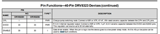
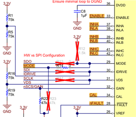
EN pin direct connect to 3v3
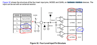
MODE pin direct connect to GND 
GAIN pin connect to GND via 47k resistor 

like in HAL_enableDRV function

GPIO_writePin(obj->gateEnableGPIO, 1);
GPIO_writePin(obj->gateModeGPIO, 0);
GPIO_writePin(obj->gateCalGPIO, 0);

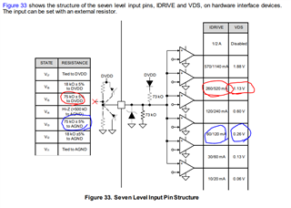
and what's the state of IDRIVE and VDS with both 75k resistor to 3v3 and GND  ?

Thanks,

Tiger

  • Hi Tiger, 

    For your specific questions on device use settings, see answers below. 
    Please help mark thread resolved if this answers your questions. Thanks!

    • EN pin direct connect to 3.3V should be ok to enable the device 
      • power sequencing might matter. when does this turn on relative to VM connection to battery voltage?
      • if you want to be able to RESET the device's fault status after a fault event without completely power-cycling the device, 
        • then you'll want to be able to toggle the ENABLE pin H/L rather than just tying it high to 3.3V permanently. See pin description of datasheet
    • HARDWARE INTERFACE connections for device settings 
      • MODE pin direct connection to GND means 6xPWM mode 
      • GAIN pin 47kOhm connection to GND means 10V/V CSA GAIN setting 


    • HARDWARE INTERFACE connections for device settings (continued) 
      • you need to pick either 75kOHM-to-DVDD or 75kOHM-to-GND for each setting, not both. 
      • see below diagram from the DRV8323 device datasheet. Red/Blue will correspond to whichever setting you bias for that specific pin

    Best Regards, 
    Andrew