This thread has been locked.

If you have a related question, please click the "Ask a related question" button in the top right corner. The newly created question will be automatically linked to this question.

DRV8244-Q1: how to use DRV8244HQRYJRQ1

Part Number: DRV8244-Q1

Hello Team,

we have encountered some problems when debugging the chip TI-DRV8244HQRYJRQ1.

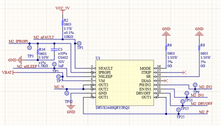
1. DRV8244HQRYJRQ1 is HW variant, we adopt PH/EN mode, and the chip settings are as follows,

Hardware: (1)connecting pin14(SR) and PIN16(MODE) to GND, disconnecting PIN15(ITRIP) and  PIN13(DIAG);

                  (2)Vbat is 12V;

Software: PIN12 (PH/IN1), pin 11 (EN/IN1), PIN3 (nSLEEP) input high level, PIN10 (DRVOFF) input low level;

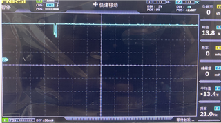
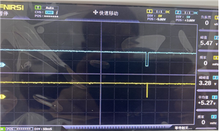
2. Output pin OUT1/OUT2 of the chip does not output, and the voltage of PIN1 (NFAULT) pin measured with multimeter is 0V.

Please help us to see if there are any problems with the schematic diagram and software settings. And tell us how to change it.

Thanks.

  • Hey Haoran,

    Do you issue the nSLEEP reset pulse during wakeup?  See 7.7.2 Wake-up Transients and 8.4.5 nSLEEP Reset Pulse (HW Variant Only).

    – HW (H) variant - Pin control is mandatory even if SLEEP function is not needed. The controller needs to issue a reset pulse (typical: 30 μsec bounded between treset max and tsleep min) during wake-up to acknowledge wake-up or power-up.  

    Regards,

    Jacob

  • Thanks for your reply.The reset pulse during wakeup may be ignored in the software settings, so we will try again to see if we can solve it.

  • Hey Haoran,

    Let me know if that solves your issue and if you need any additional support.  Thanks!

    Regards,

    Jacob

  • Thanks for your help, we have solved it .If there is a problem in the follow-up, we also need your help.

  • 嘿雅各布,

    现在,我们有了一个新的问题,

    当电机移动时,它移动约3秒,然后产生约10毫秒的停止。我用示波器测量了引脚OUT1的波形,如图1所示

    NSLEEP引脚波形如下图所示的蓝线所示,NFAULT引脚波形如下图所示的黄线所示。

    请帮我检查是否有任何问题。

  • Hello,

    I've translated your question below for my own convenience:  

    Hey Jacob,

    Now, we have a new question,

    When the motor moves, it moves for about 3 seconds and then stops for about 10ms. I measured the waveform of pin OUT1 with an oscilloscope as shown in Figure 1.  (First picture)

    The NSLEEP pin waveform is shown in the blue line shown in the figure below, and the NFAULT pin waveform is shown in the yellow line shown in the figure below. (Second picture)

    Please help me to check if there is any problem.

    Is the second picture showing your wake-up procedure with the nSLEEP reset pulse?  Or is second picture showing NSLEEP and nFAULT at the time of the 10ms where the motor stops driving?  It looks like the wake-up procedure to me. 

    In the first picture, can you check the current and the supply voltage at this time to make sure that it isn't tripping OCP or UVP?  

    Regards,

    Jacob

  • Hello,

    Let me add more comment. Although I cannot read your language, looks like your issue is motor stop after 3 sec spinning. It could be OCP or UVP or TSD.

    -For OCP, suggest to capture output current when nFAULT goes low by fault detection.

    -For UVP, suggest to capture output current when nFAULT goes low by fault detection.

    -For TSD(Thermal shut down), it is key that GND pins/pad connect to GND plan of PCB through thermal via.

    www.ti.com/.../slva959b.pdf

    If motor current is high with long duration, TSD may happens. Following table can be referred.

    regards

    Shinya Morita

  • Hi team,

    I am very sorry that due to the Chinese National Day holiday, I did not reply in time. Thanks for your help, we have solved it .If there is a problem in the follow-up, we also need your help.

  • Hi Jacob,

    I am very sorry that due to  Website Maintenancethe and the Chinese National Day holiday, I did not reply in time. Thanks for your help, we have solved it .If there is a problem in the follow-up, we also need your help.Thank you very much.